


SIG Four-Star 60 Build
 03-15-2019, 11:43 PM
#26

Thread Starter
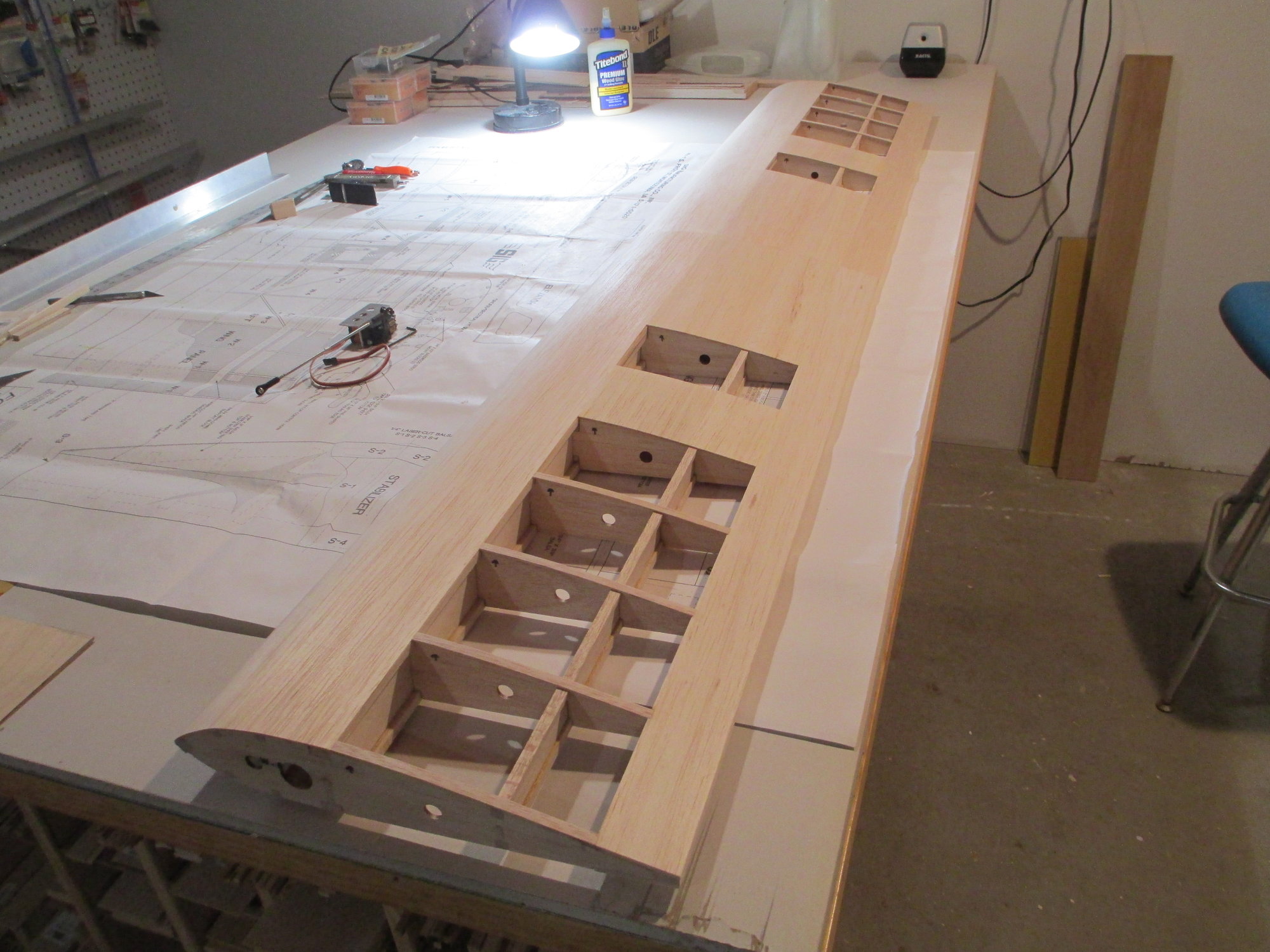
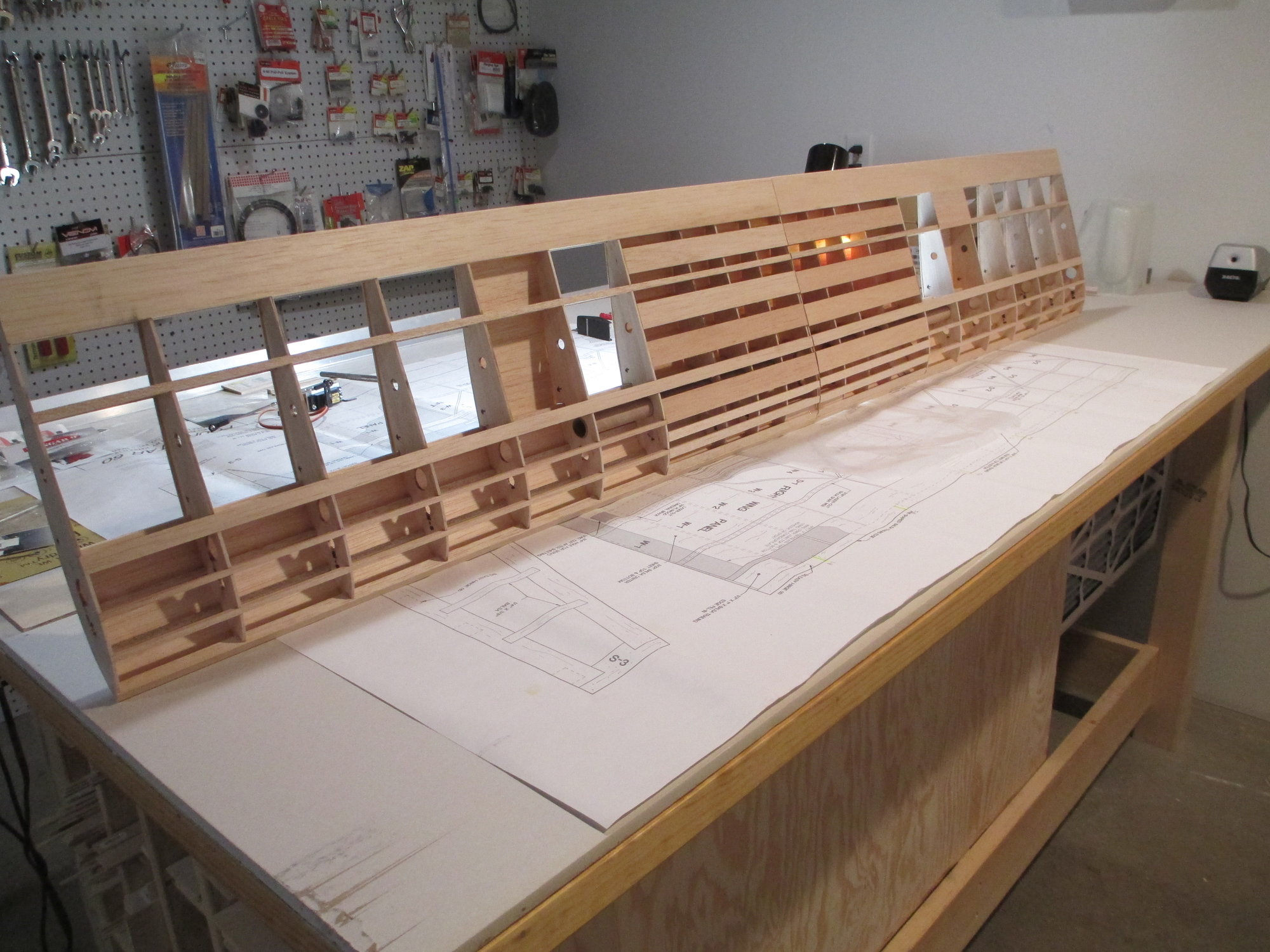
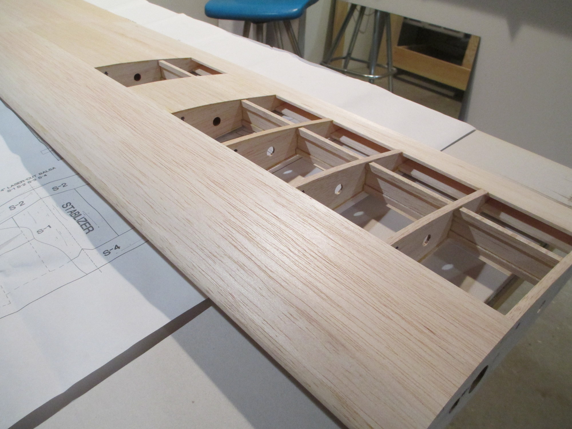
Sheeting the leading edge section as I have done as well as boxing in the center aileron section, has stiffened up the wing considerably which is why I eliminated all of the cross bracing. Time and use will tell if I'm right...
Last edited by VincentJ; 03-15-2019 at 11:46 PM.
 03-16-2019, 07:07 AM
#27
Thread Starter
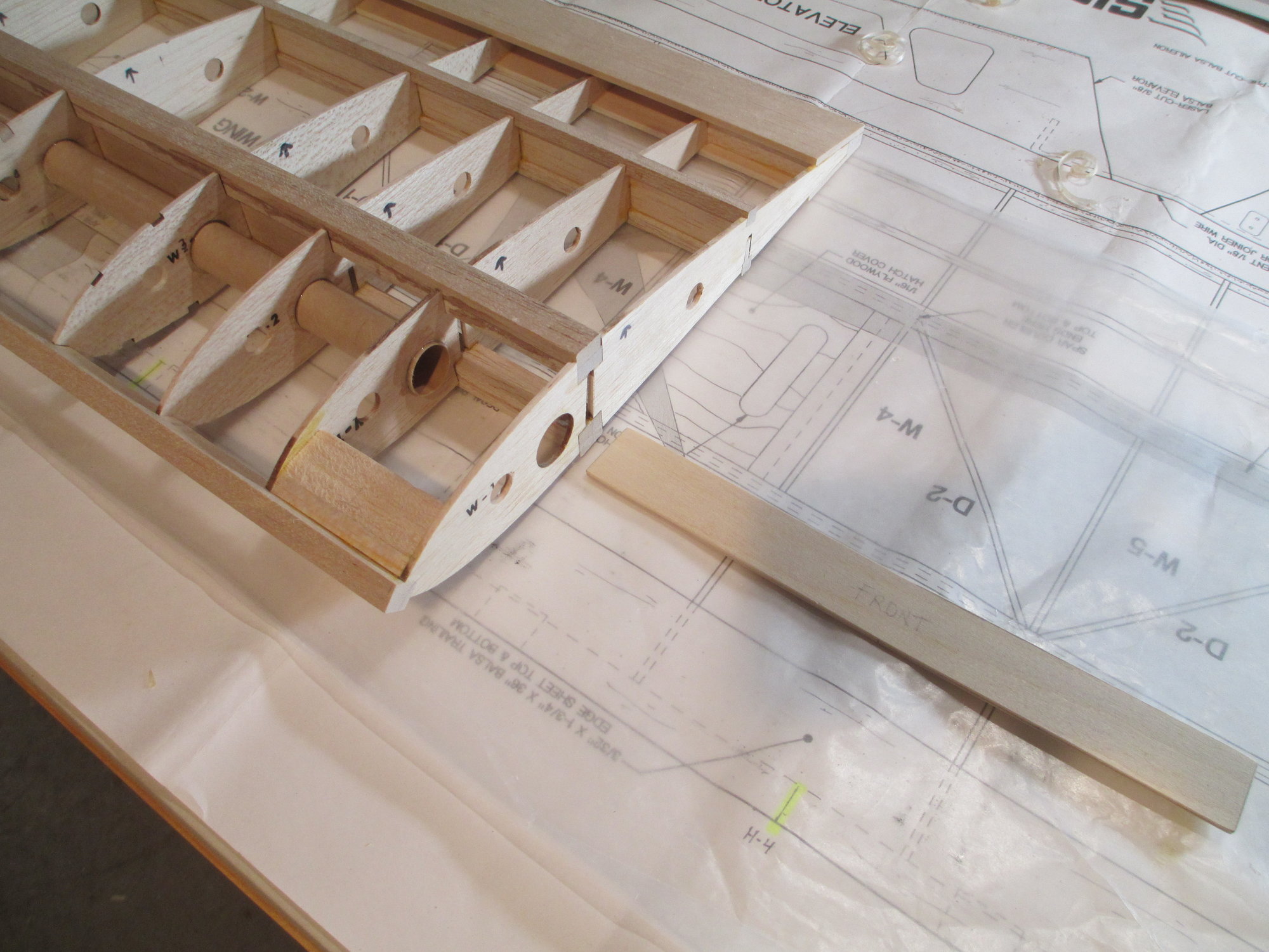
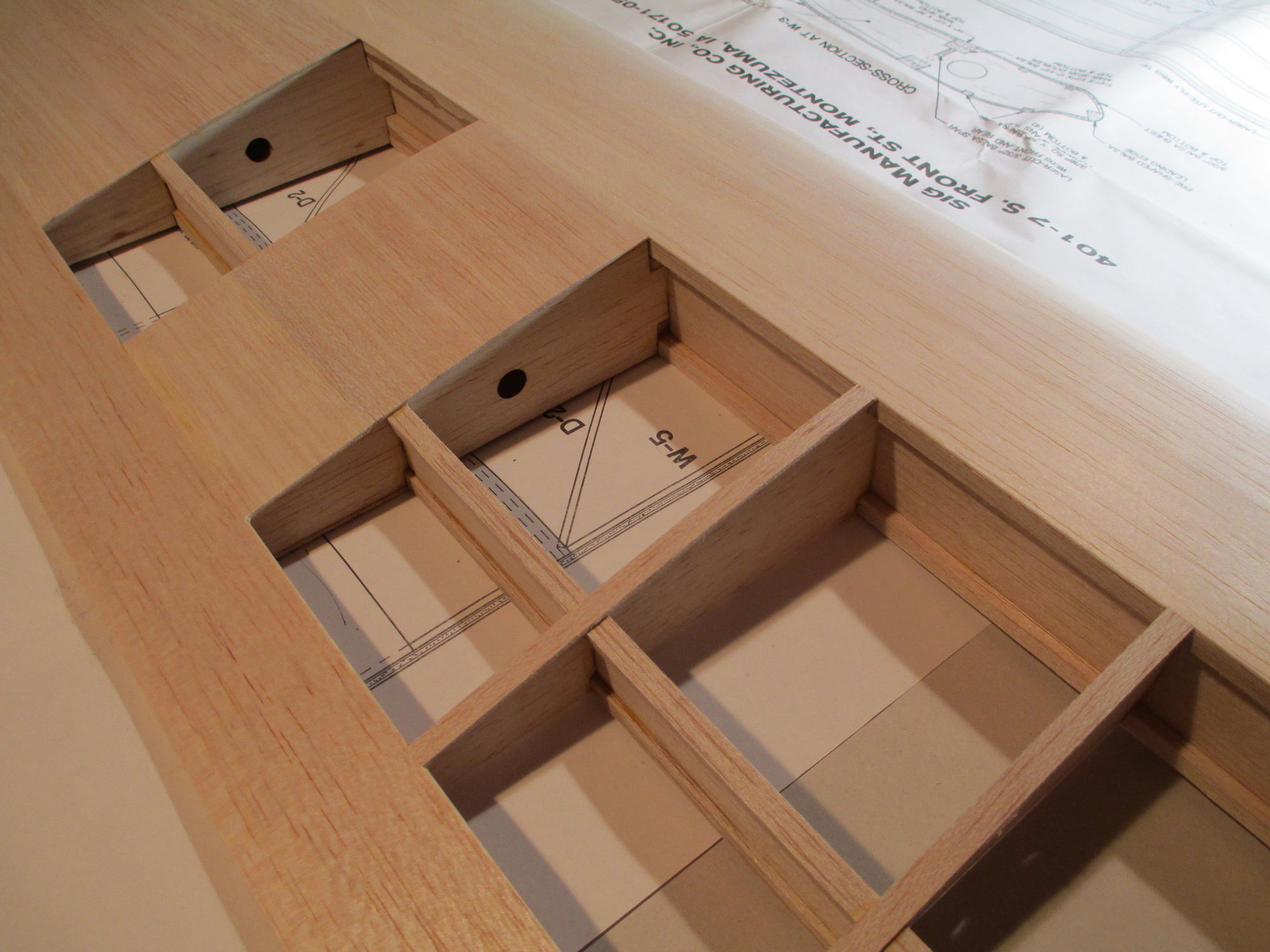
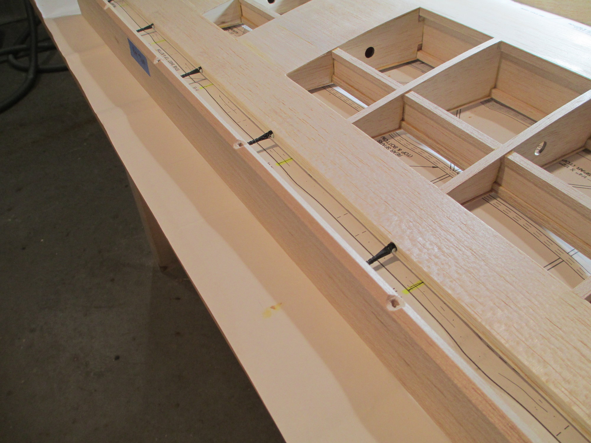
Right wing panel and the new plywood wing joiner. I scrapped the supplied wing joiner that would have given the wing its 2 degrees of dihedral (per panel) and made a new one set at 1 degree.
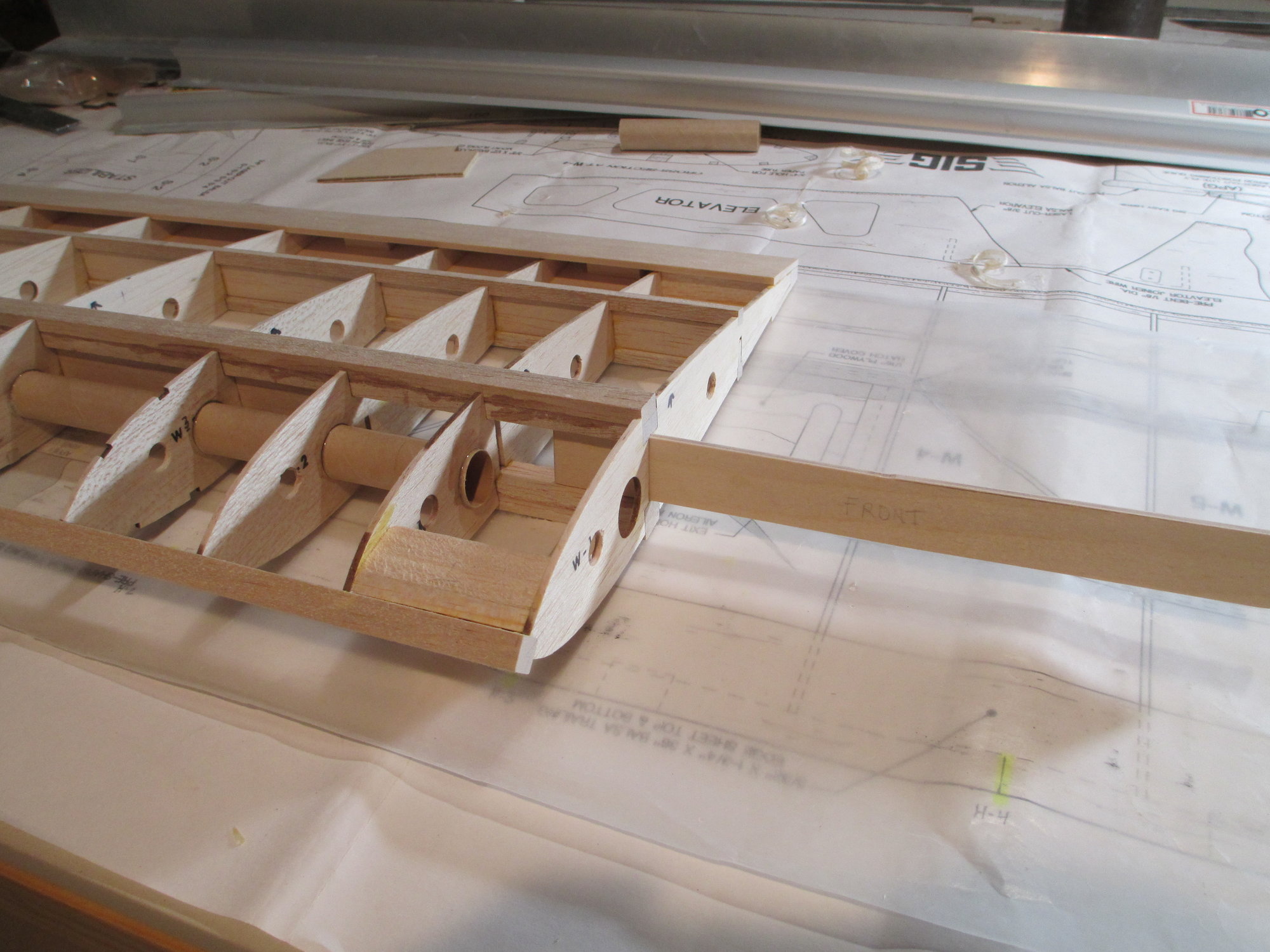
The wing joiner is being slid through ribs 1 and 2 and should fit snug between the top and bottom wing spar.
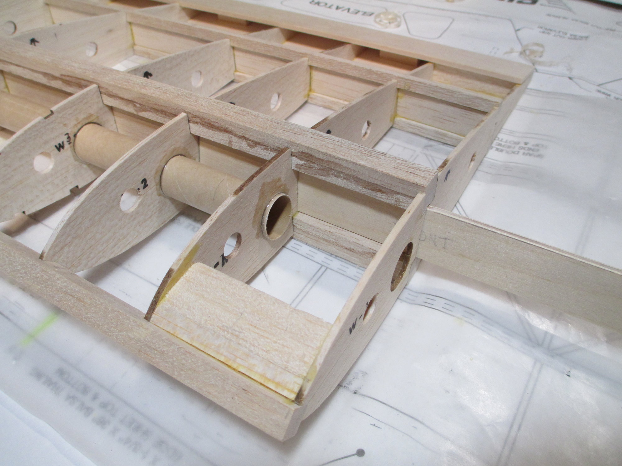
The wing joiner is now completely in and I'm happy with the fit.
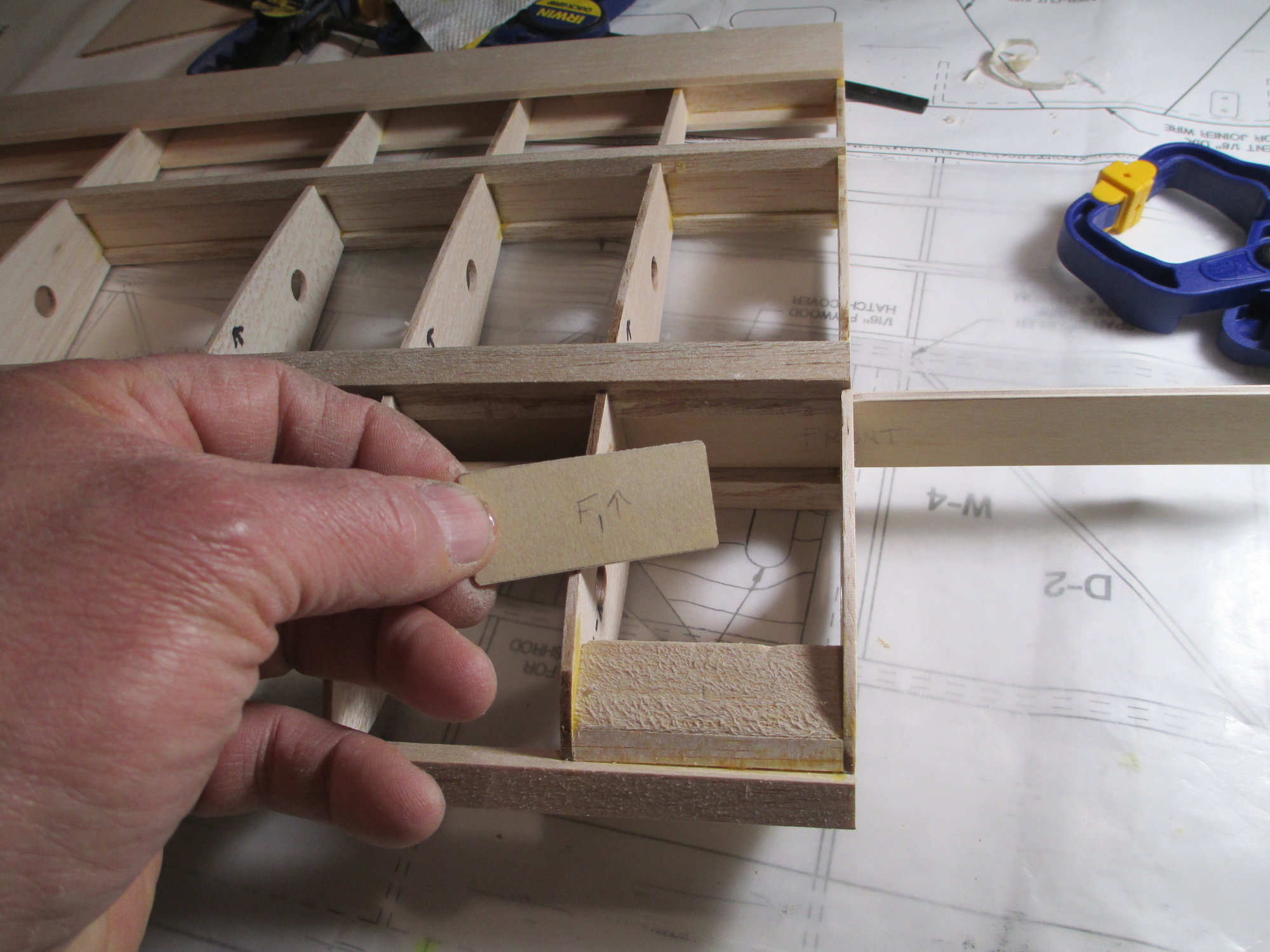
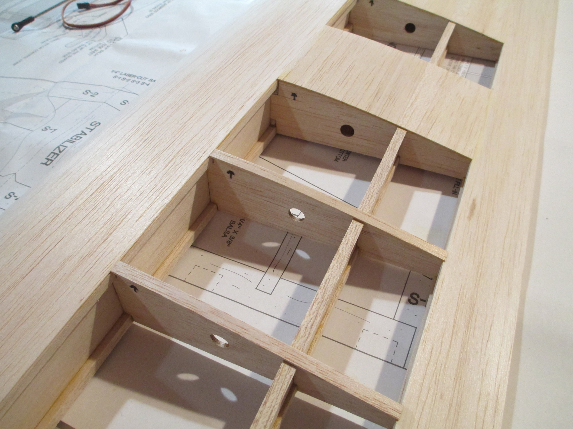
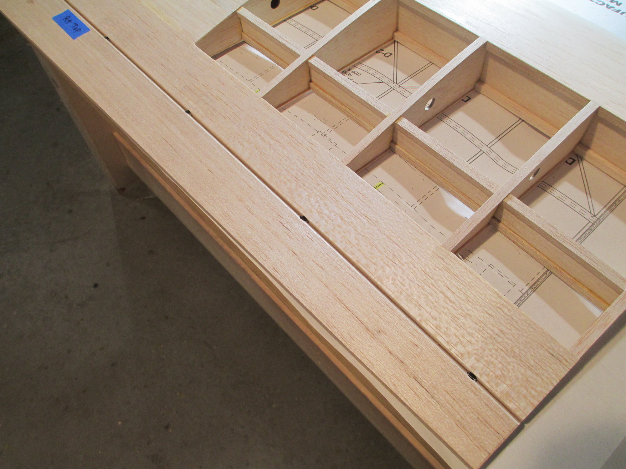
I want to ensure that the joiner is permanently epoxied into position but with the additional insurance of it being sandwiched between four plates made from 1/16" birch ply.
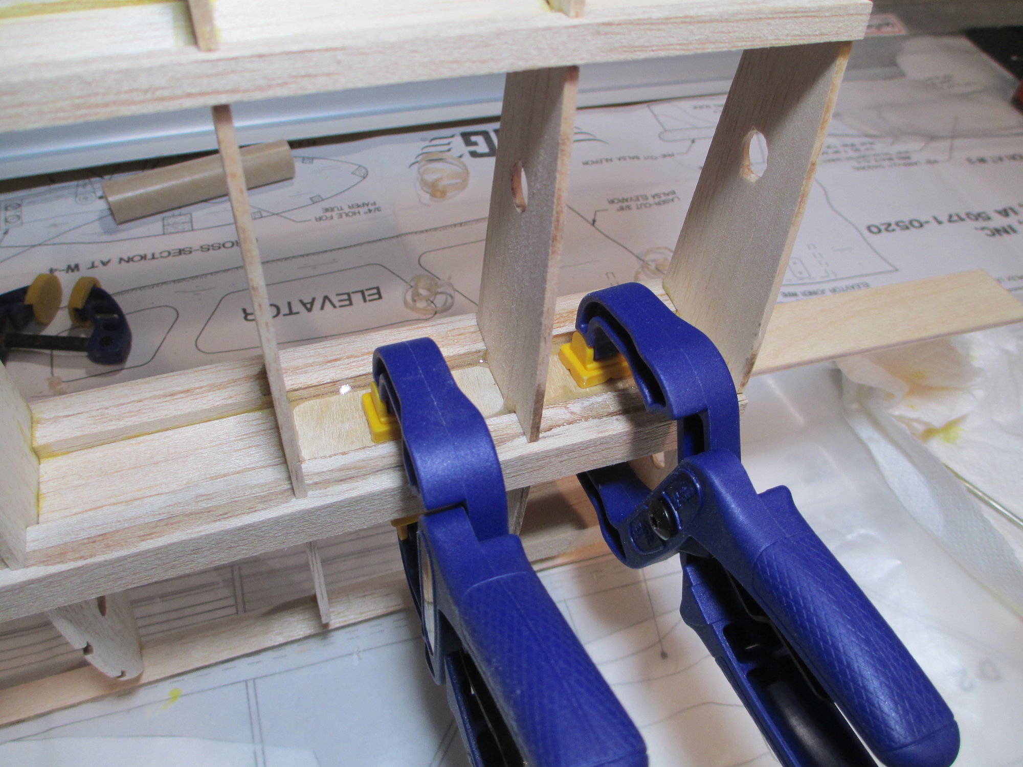
Epoxy was spread on both sides of ribs 1 and 2 and plywood plates are now clamped into position. I like the squeeze out that I got, the fillet of epoxy will stay.
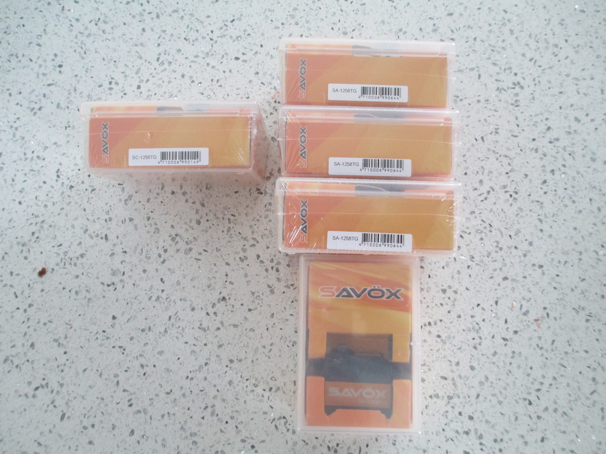
I want to give a big shout out to amain hobbies. I ordered my servos on Thursday, March 14th and received them today! Great service, fair prices and I didn't have to pay for shipping because of the total amount spent. Check them out.
https://www.amainhobbies.com/rc-cars-trucks/c1?utm_source=transactional_email&utm_medium=e-mail&utm_campaign=order_update&utm_cid=1827475&utm_content=%2frc-cars-trucks
Last edited by VincentJ; 03-17-2019 at 12:06 AM.
The following users liked this post:
Wully (12-21-2021)
03-17-2019, 11:53 AM
#28
Thread Starter
Happy Saint Patrick's Day!!!
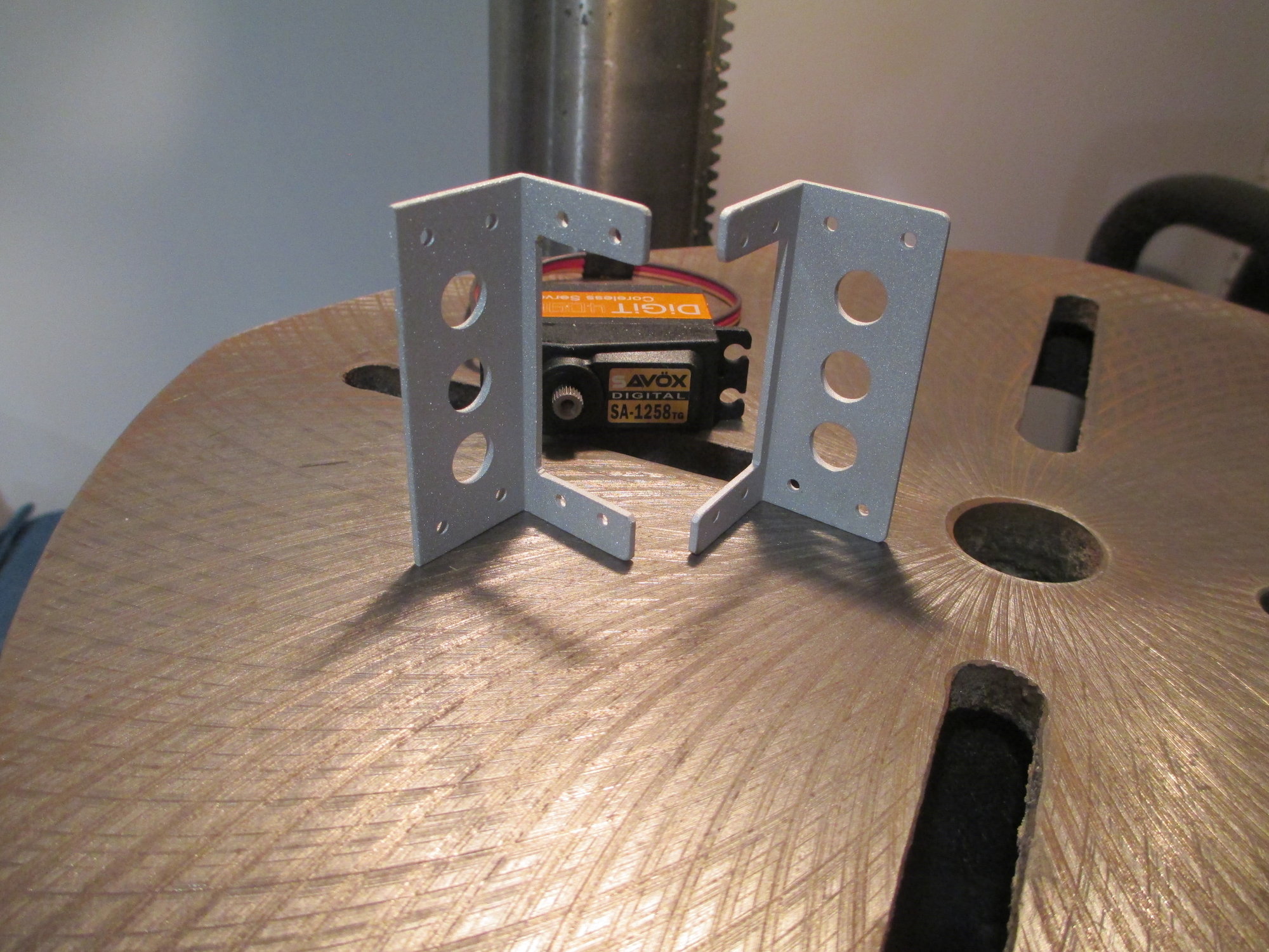
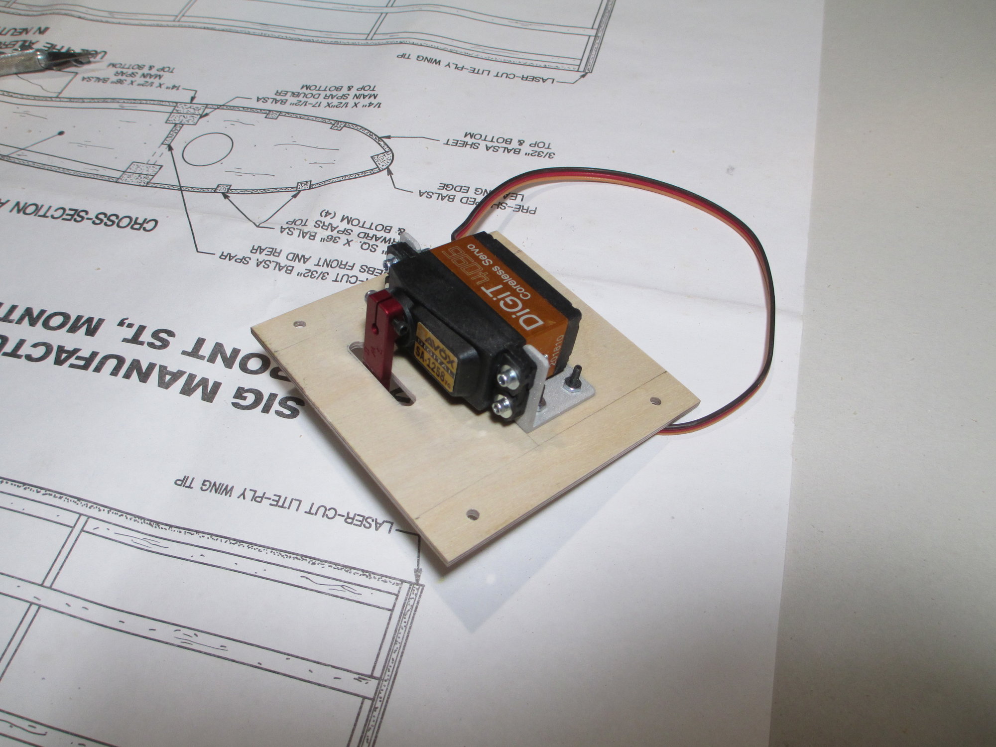
I joined the left and right wing panels this morning and while the epoxy sets, I thought I would take this opportunity and give a short tutorial on how I make servo brackets. These brackets are bullet proof and I've made them for all of my planes no matter the size. They can be made for a little bit of time and very short money. The aluminum angle stock is 1"x1" and is 1/16" thick. They can be found in most hardware stores or Home Depot.
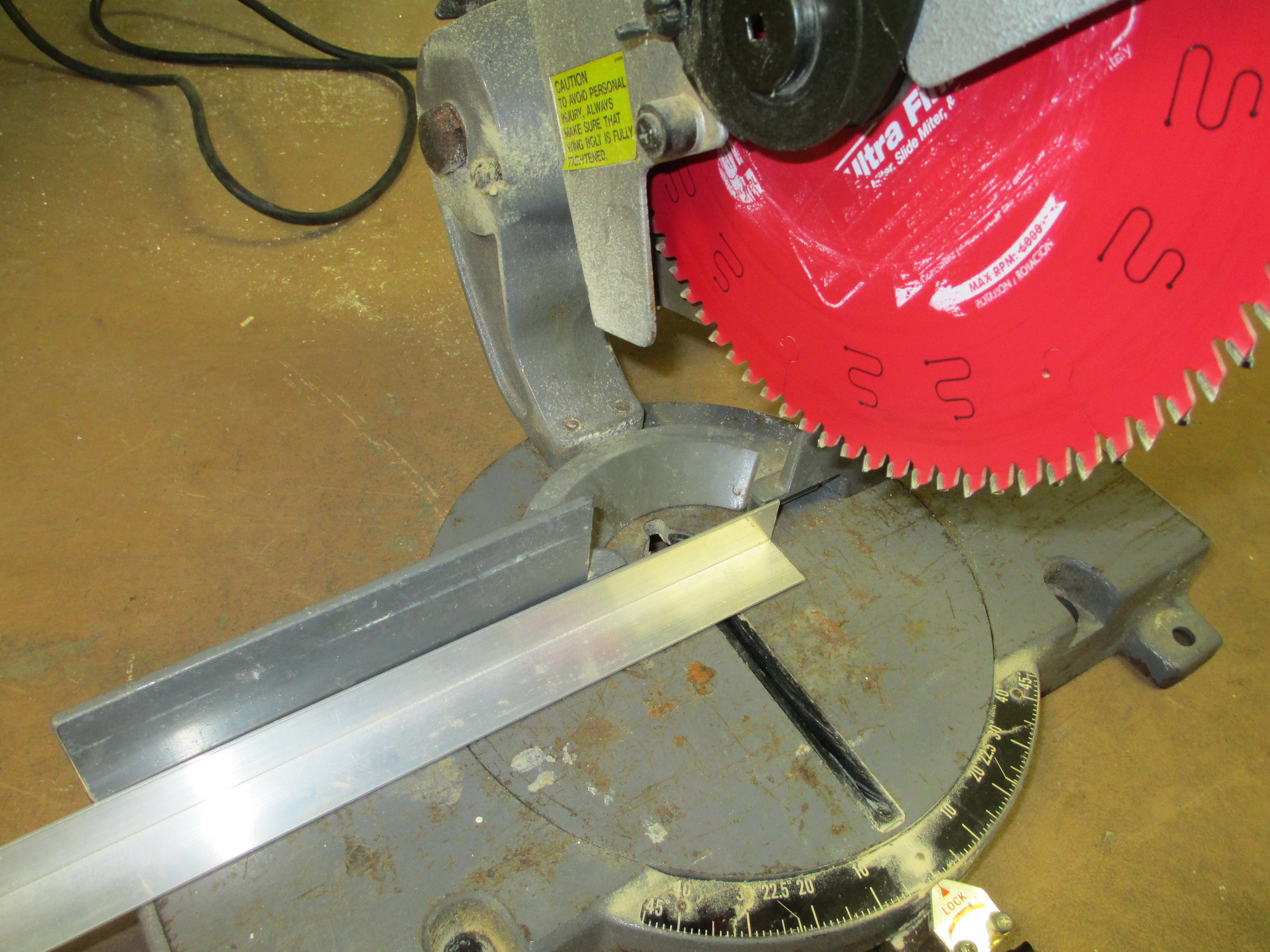
The aluminum angle stock can easily be cut with a chop saw equipped with a wood blade.
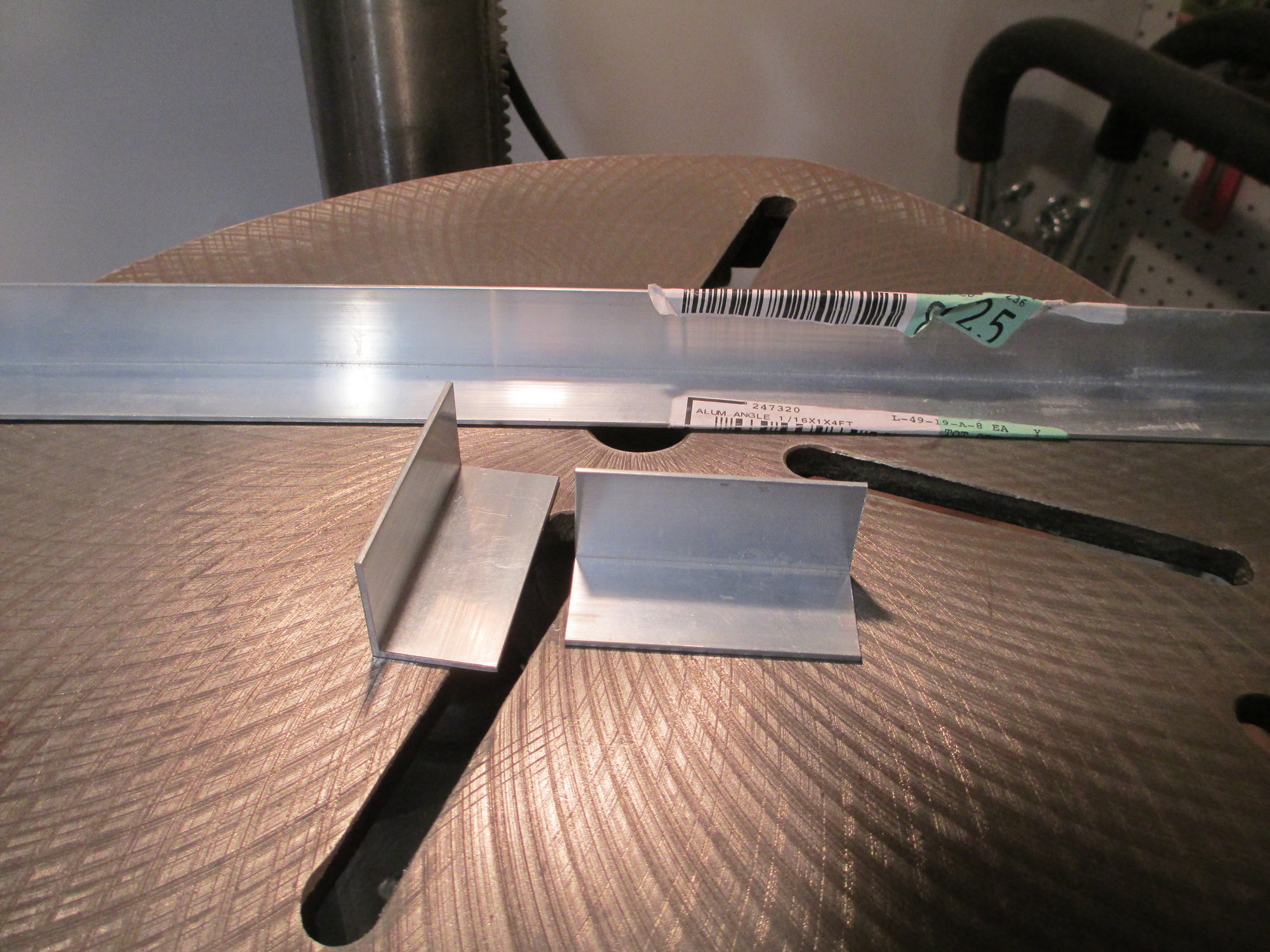
Two pieces were cut for the right and left aileron servos.
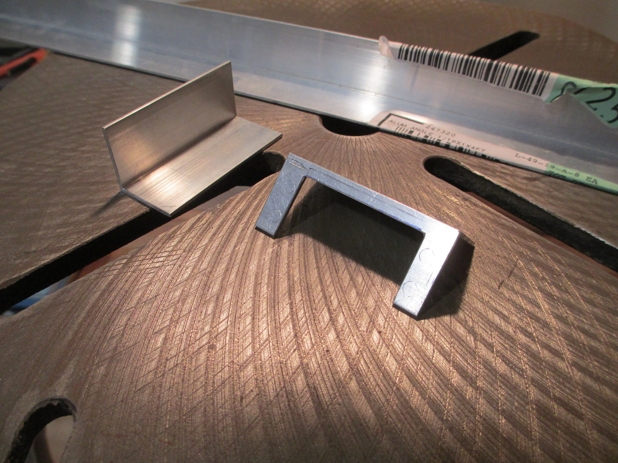
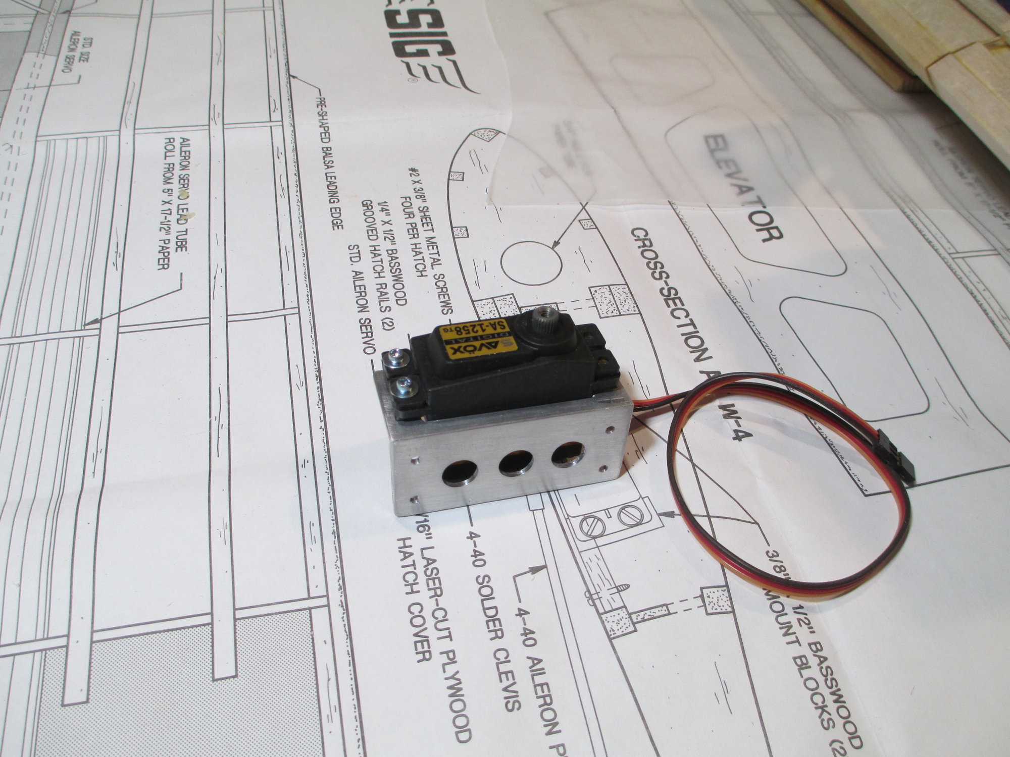
It's best if you have the servos before you start this project because a notch will need to be cut out for the servo. This will ensure that your custom bracket fits perfectly as servo sizes vary.
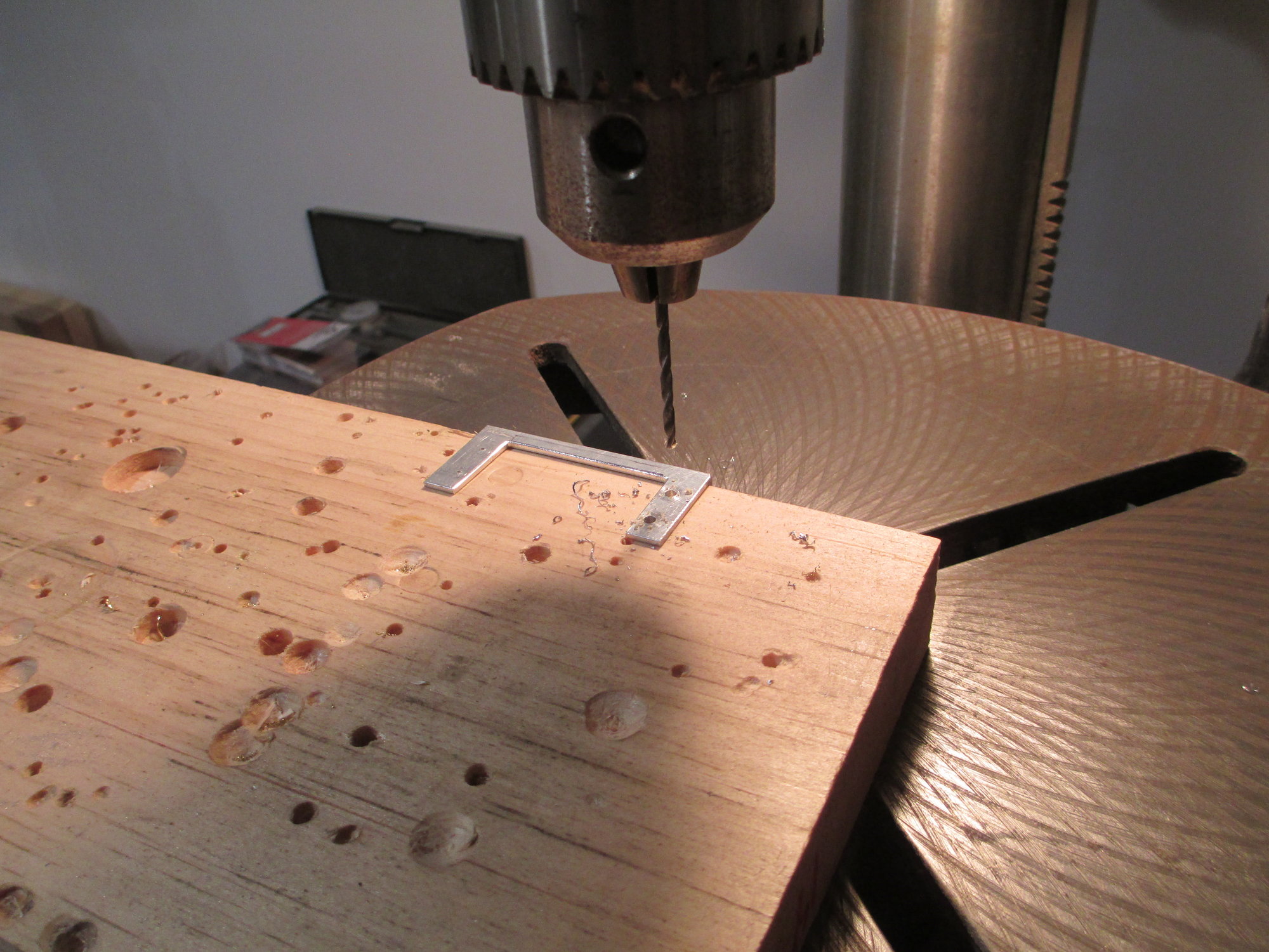
I scribed, center punched and drilled four servo mounting holes in the bracket.
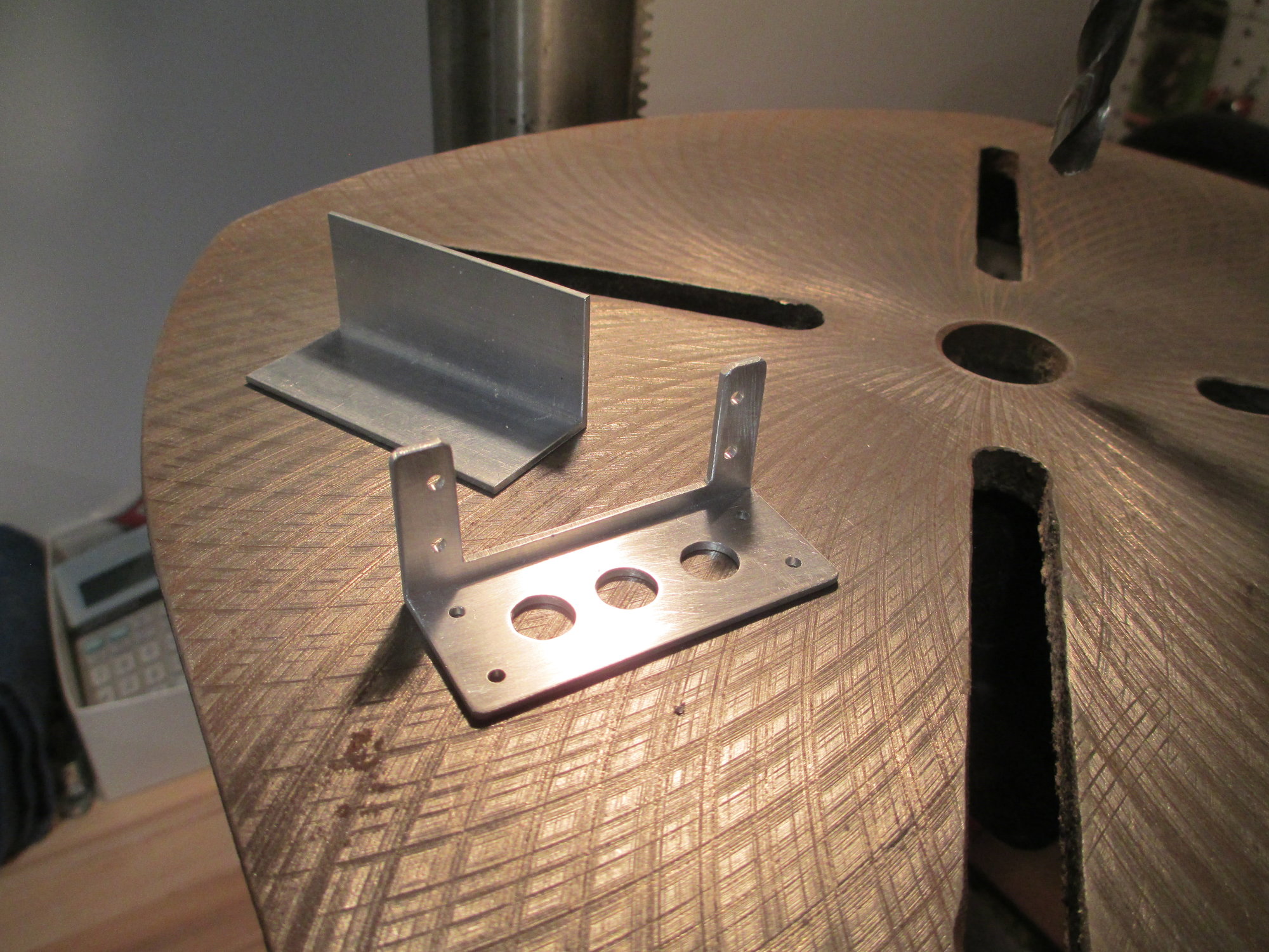
Four holes were drilled on the bottom of the bracket which secures the bracket to the plywood servo hatch. Three lightening holes were also drilled.
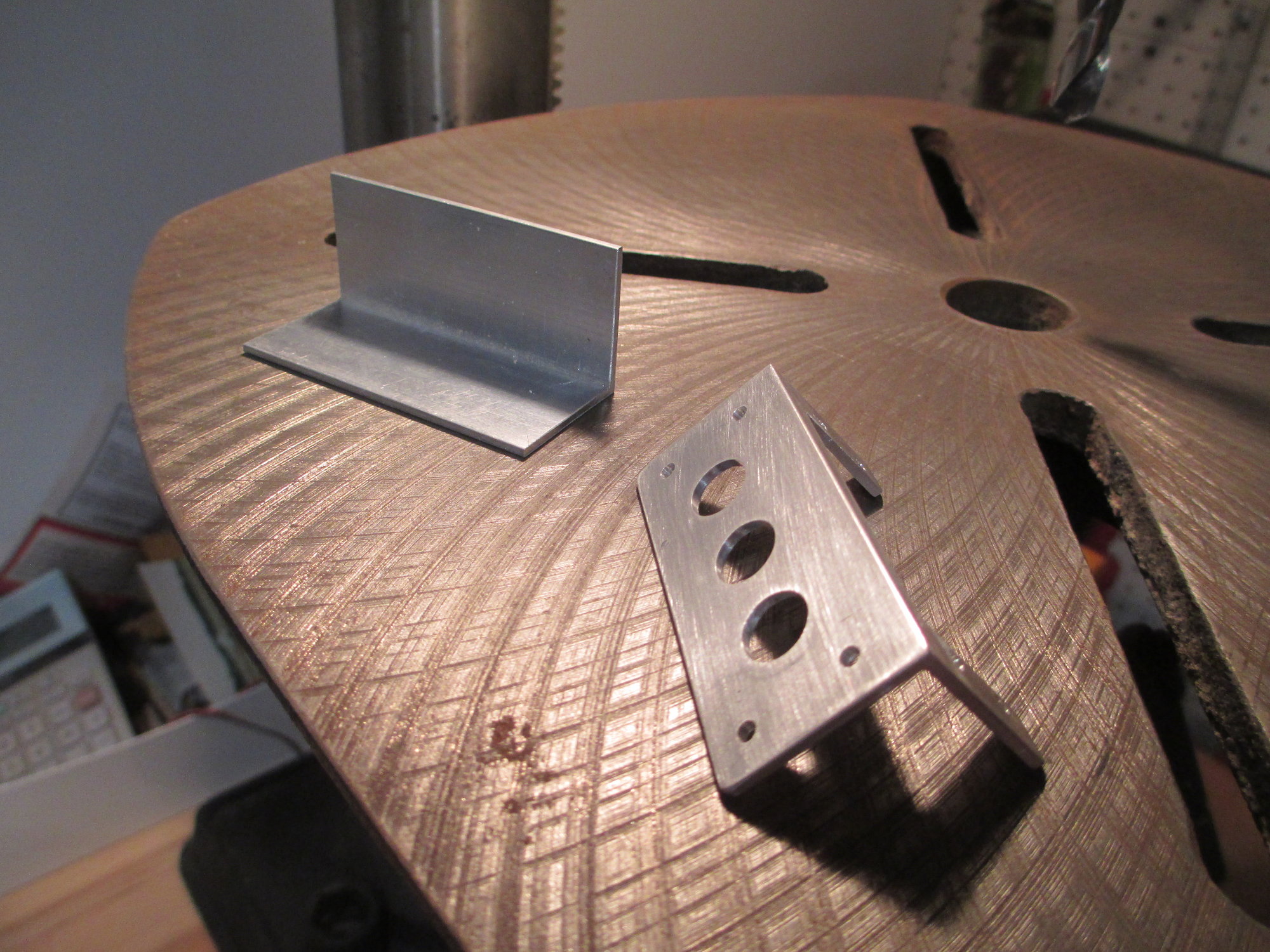
A little bit of filing and sanding is all that's left! I think it took me about 20 minutes to make this bracket.
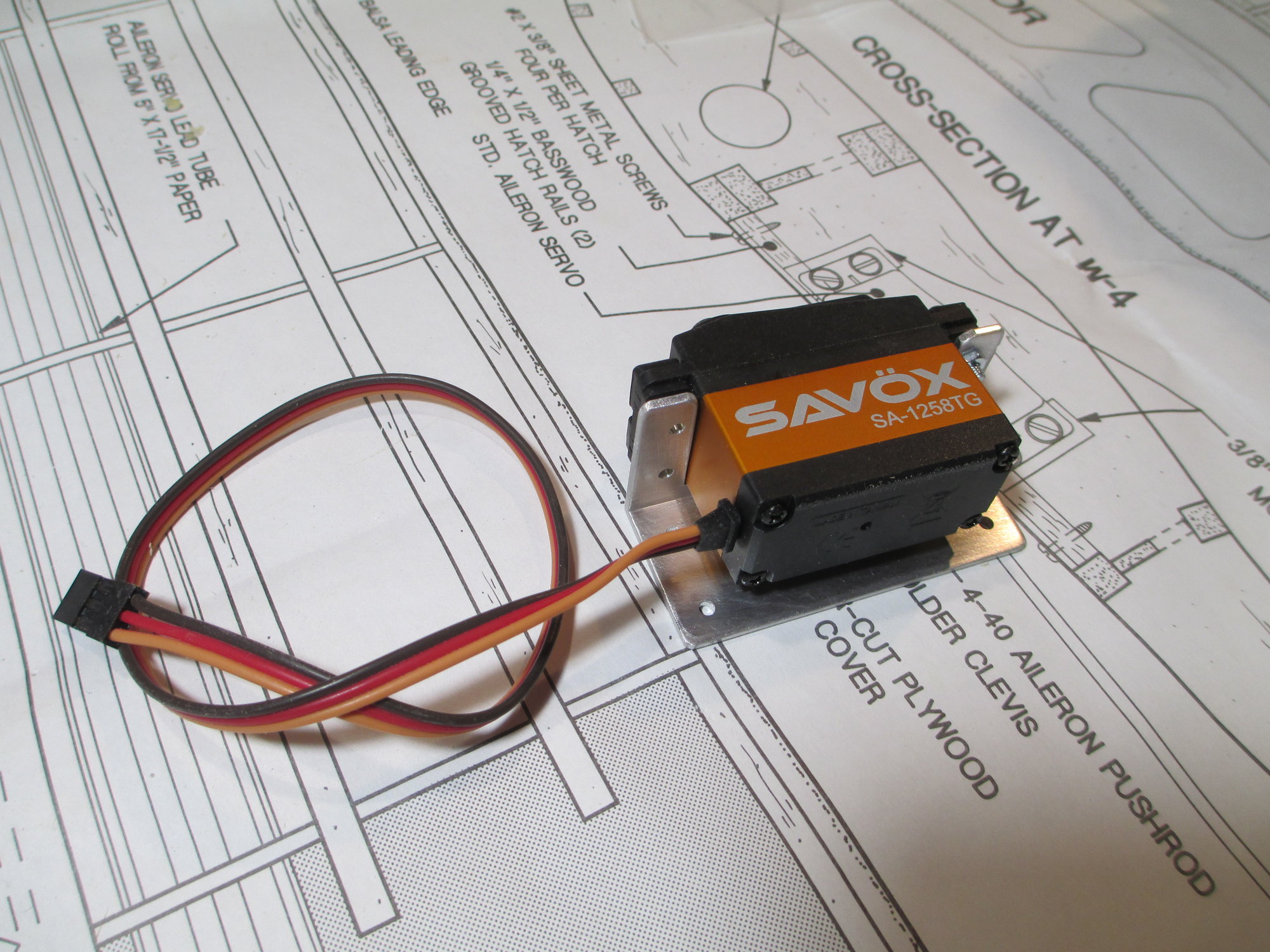
Four 2-56 x 1/2" cap head screws secures the servo to the bracket.
Make sure the servo doesn't make contact with the notch cut into the bracket, this will isolate the vibration from your air frame shortening the life of your servo.
I joined the left and right wing panels this morning and while the epoxy sets, I thought I would take this opportunity and give a short tutorial on how I make servo brackets. These brackets are bullet proof and I've made them for all of my planes no matter the size. They can be made for a little bit of time and very short money. The aluminum angle stock is 1"x1" and is 1/16" thick. They can be found in most hardware stores or Home Depot.
The aluminum angle stock can easily be cut with a chop saw equipped with a wood blade.
Two pieces were cut for the right and left aileron servos.
It's best if you have the servos before you start this project because a notch will need to be cut out for the servo. This will ensure that your custom bracket fits perfectly as servo sizes vary.
I scribed, center punched and drilled four servo mounting holes in the bracket.
Four holes were drilled on the bottom of the bracket which secures the bracket to the plywood servo hatch. Three lightening holes were also drilled.
A little bit of filing and sanding is all that's left! I think it took me about 20 minutes to make this bracket.
Four 2-56 x 1/2" cap head screws secures the servo to the bracket.
Make sure the servo doesn't make contact with the notch cut into the bracket, this will isolate the vibration from your air frame shortening the life of your servo.
Last edited by VincentJ; 03-18-2019 at 01:01 AM.
03-17-2019, 01:49 PM
#29
Thread Starter
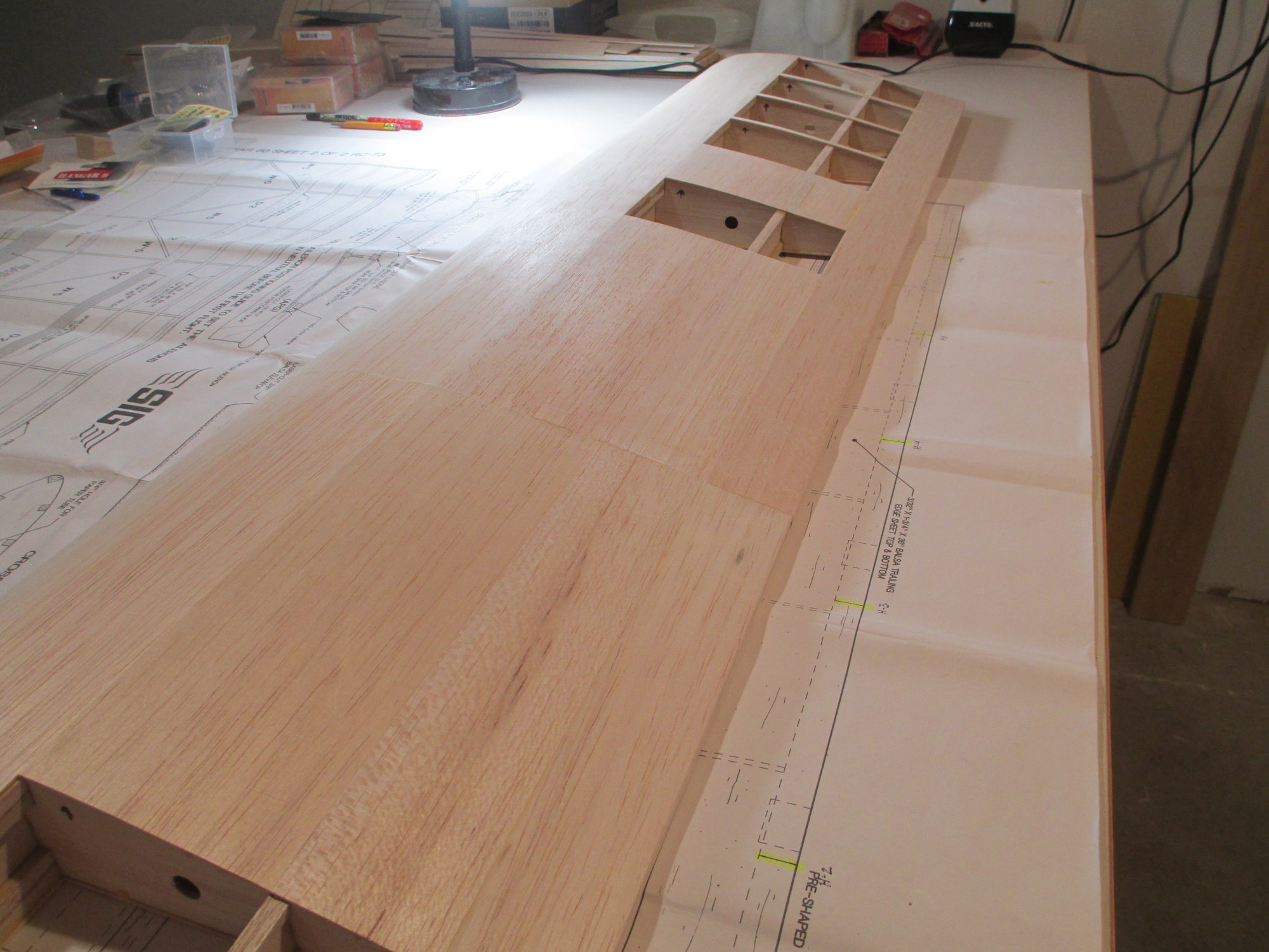
The wing panels are finally joined!
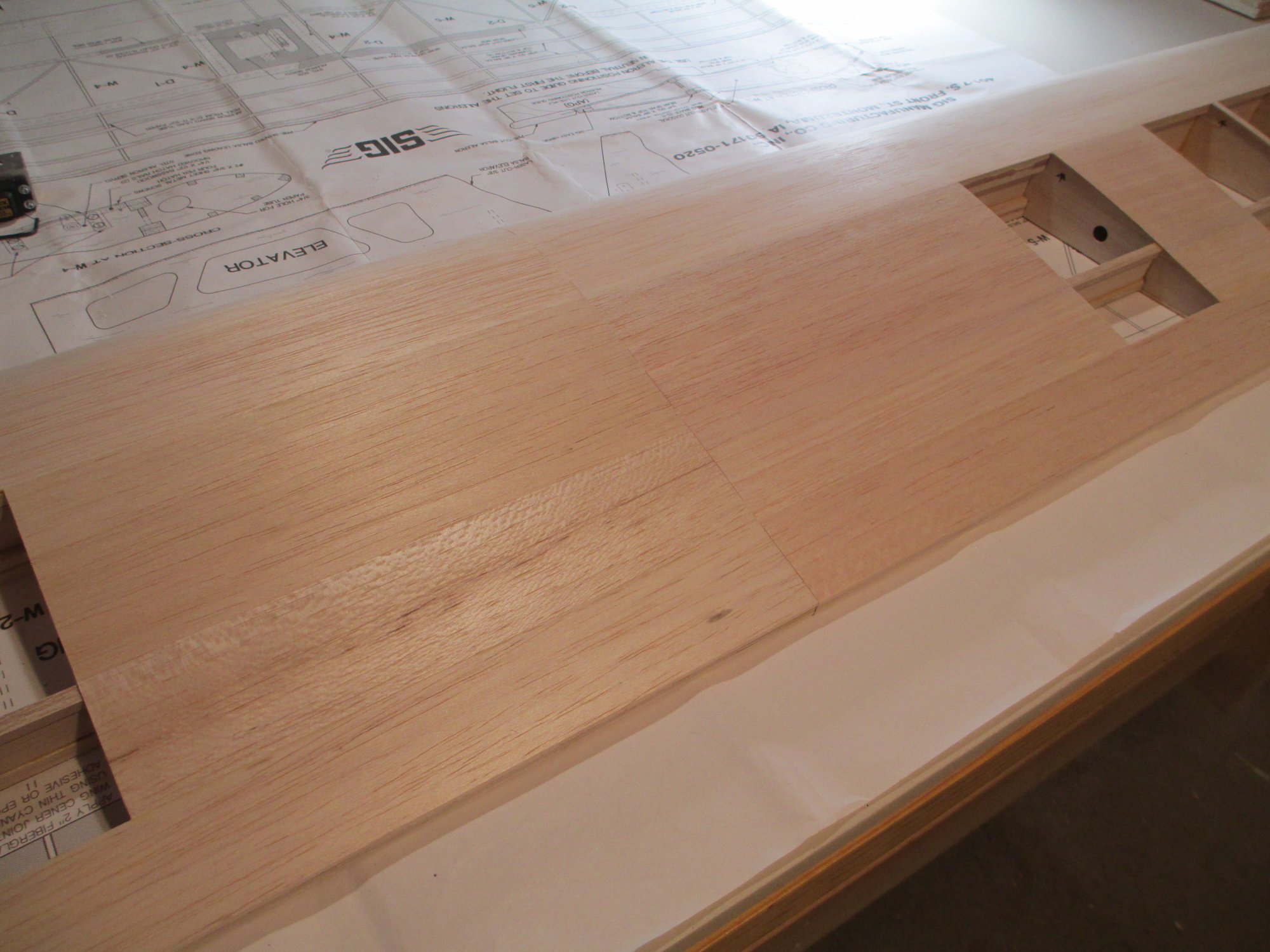
Once the bottom of the wing is sheeted, the center section seam will get wrapped with a fiberglass strip.
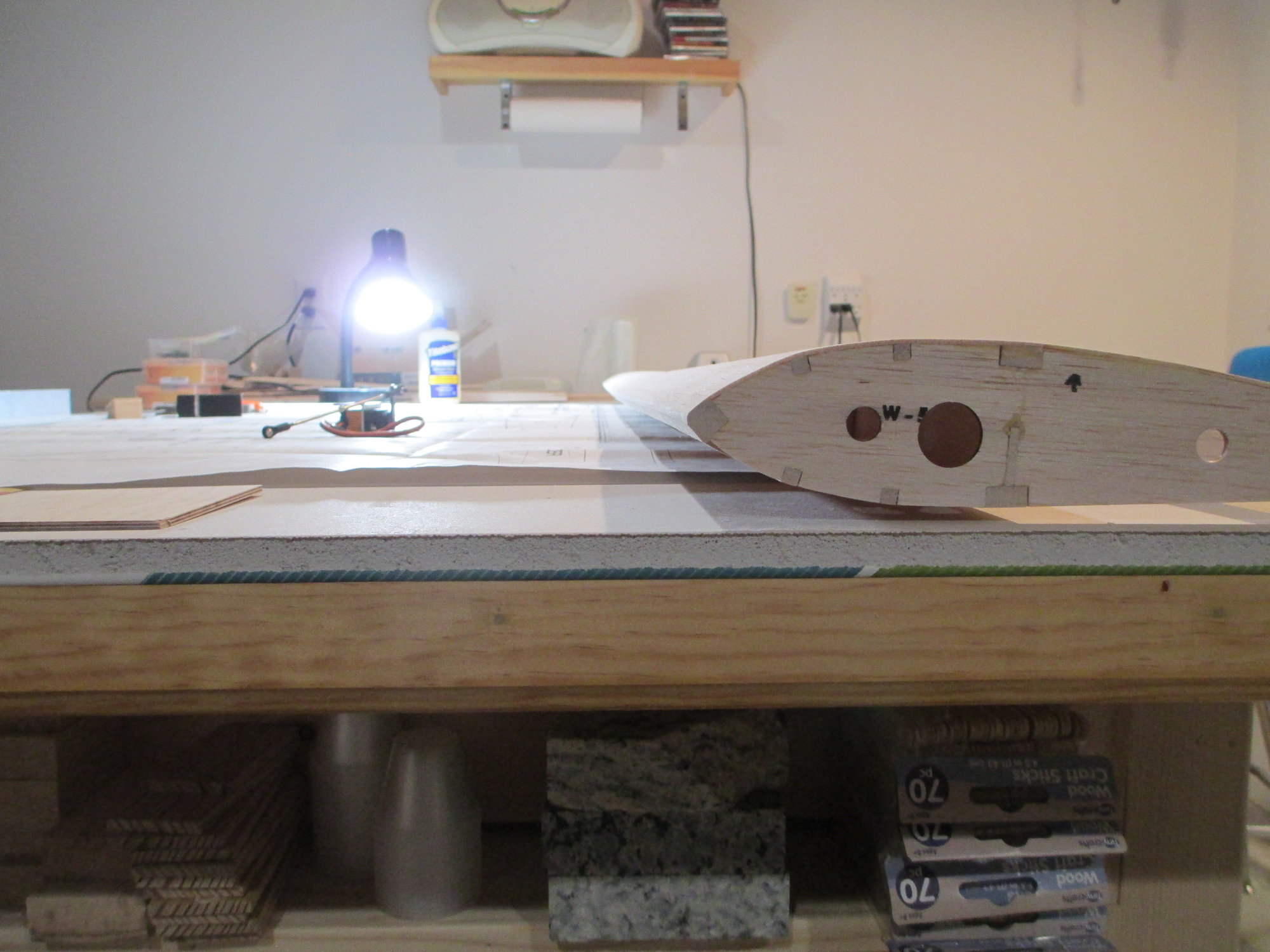
You can see the wing's dihedral in this shot.
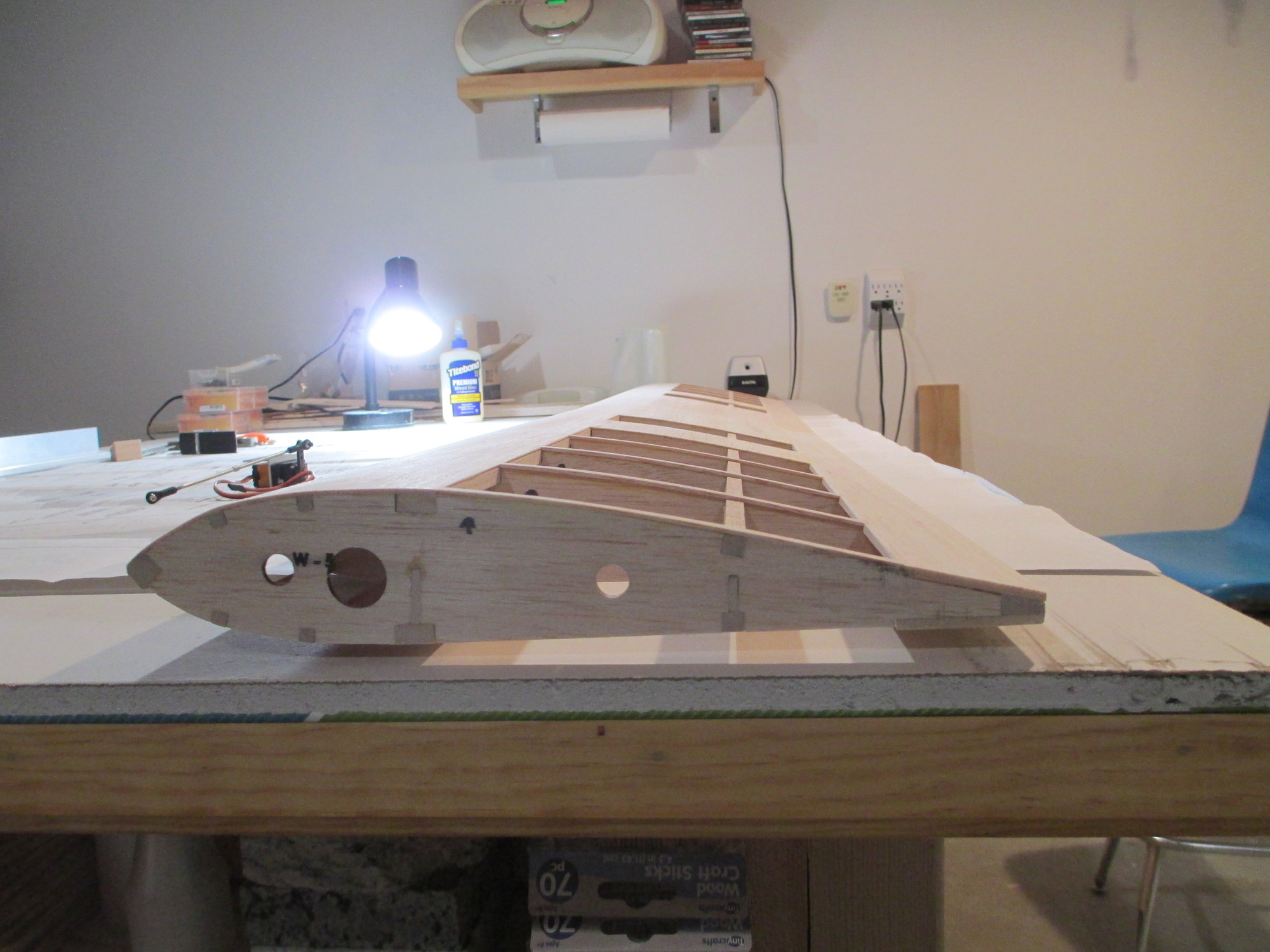
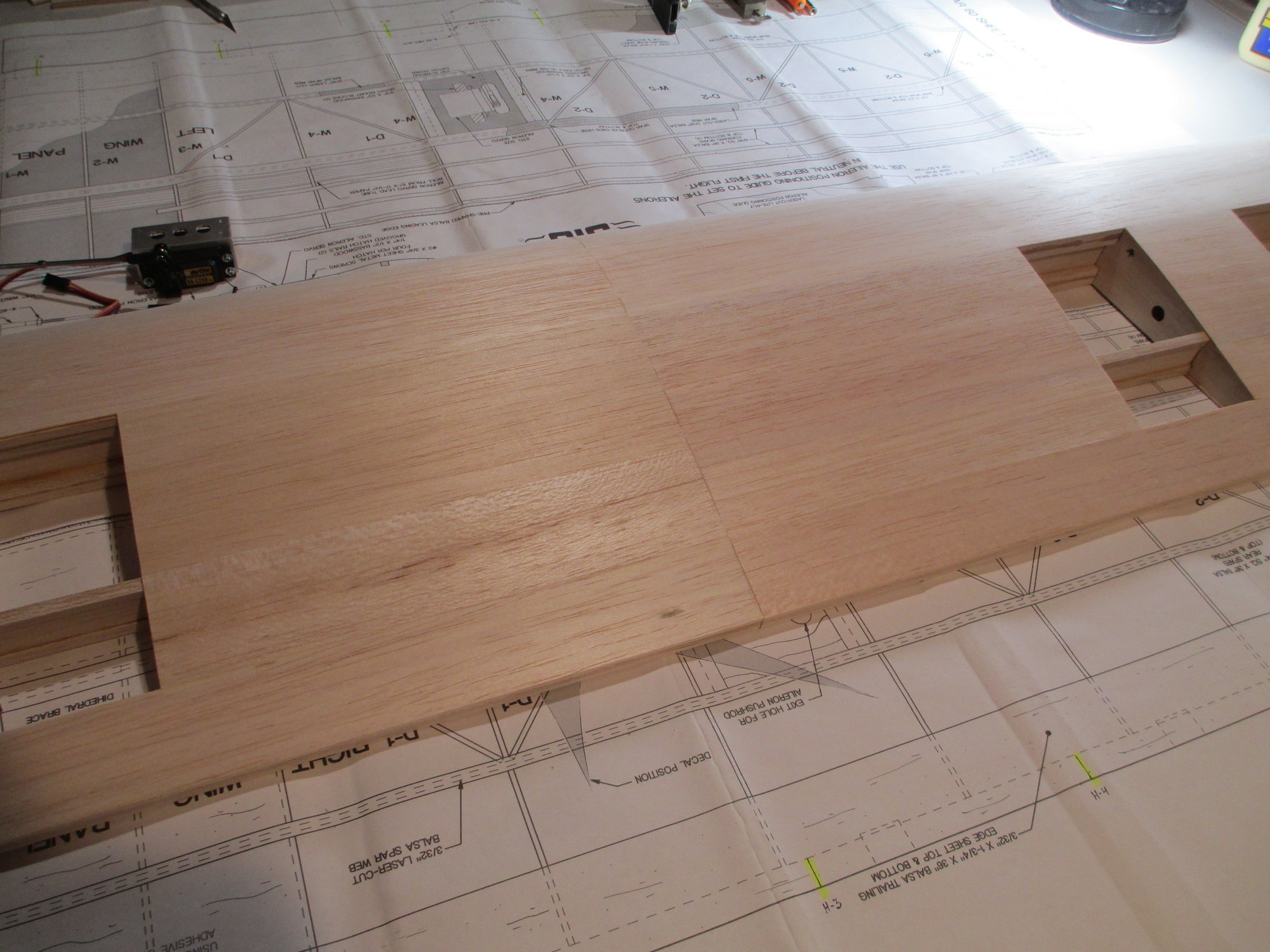
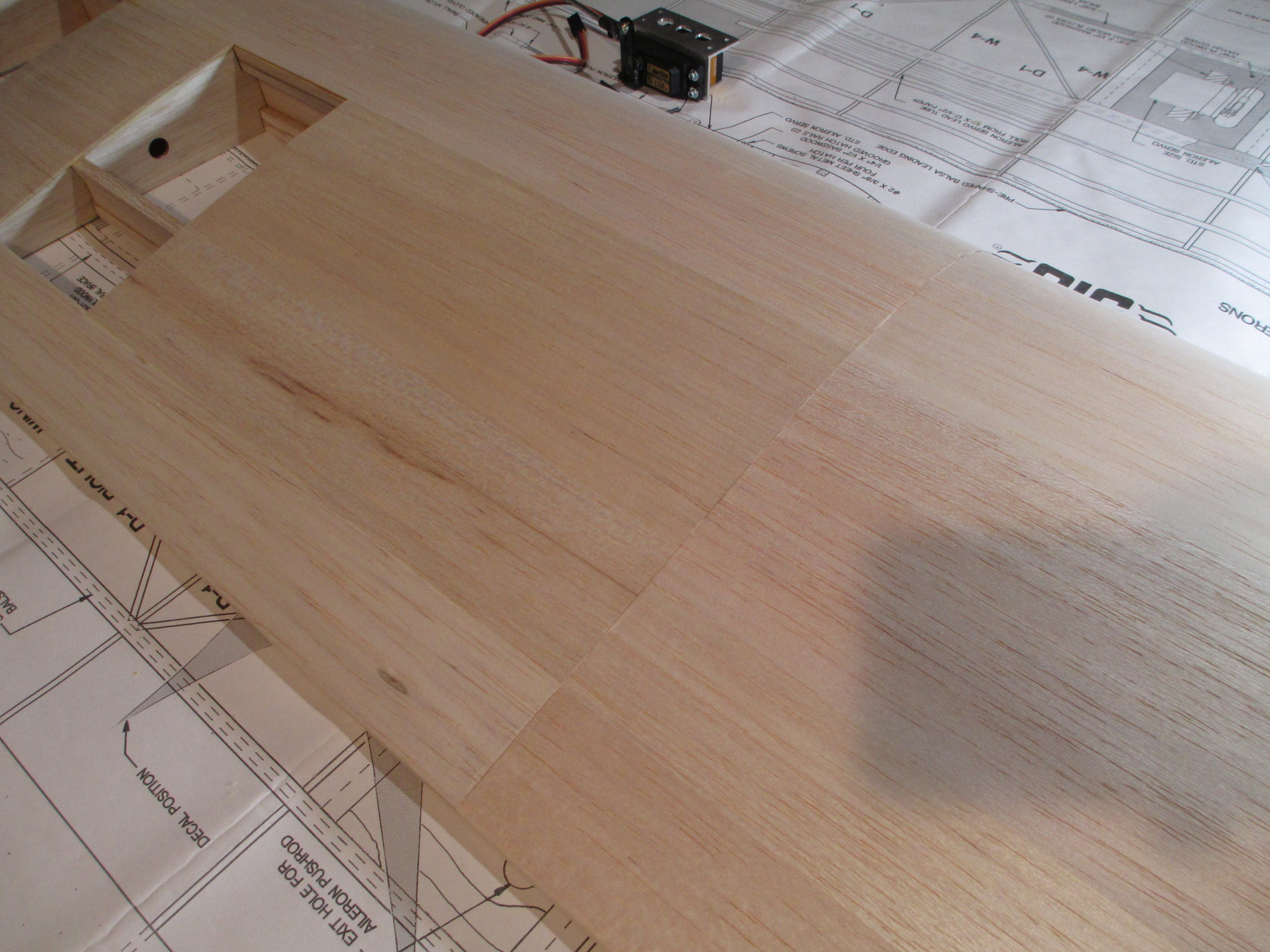
By not sheeting the bottom, I was able to make sure the epoxy was applied where I want it on the wing joiner.
Last edited by VincentJ; 03-18-2019 at 03:46 AM.
The following users liked this post:
Wully (12-21-2021)
03-18-2019, 03:07 PM
#30
Thread Starter
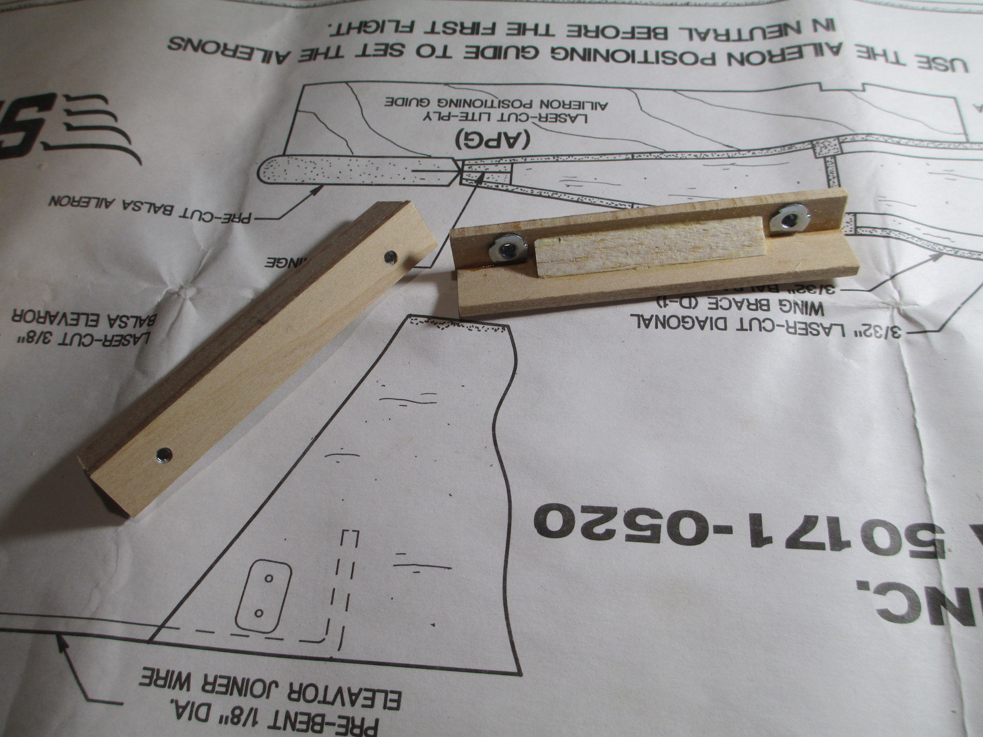
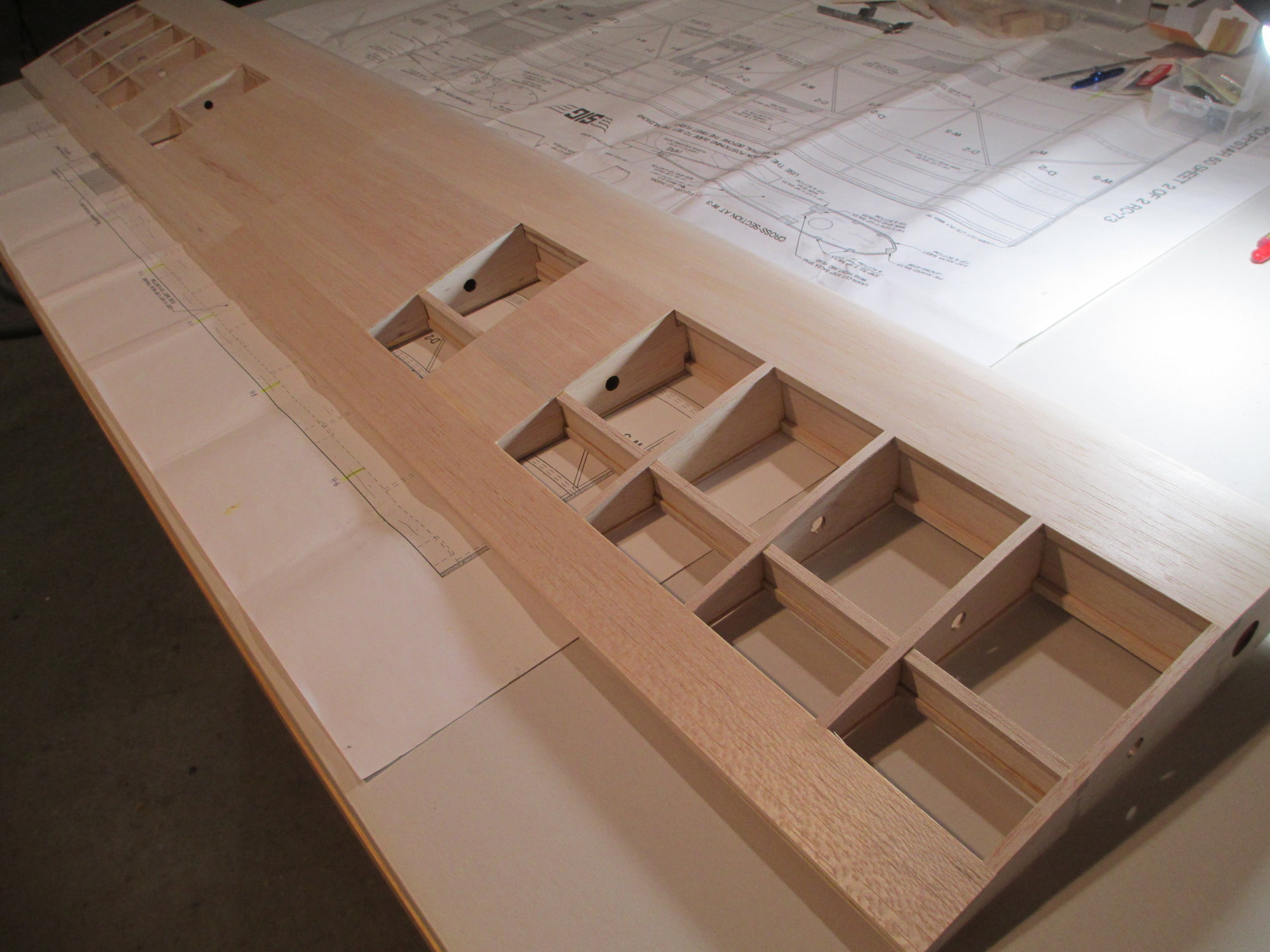
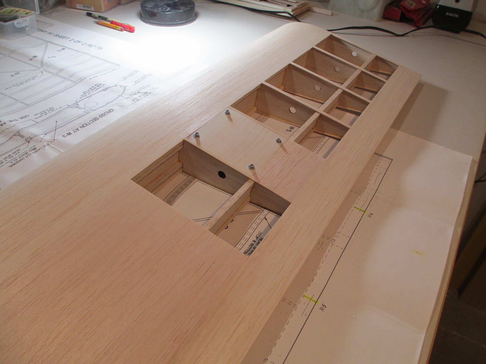
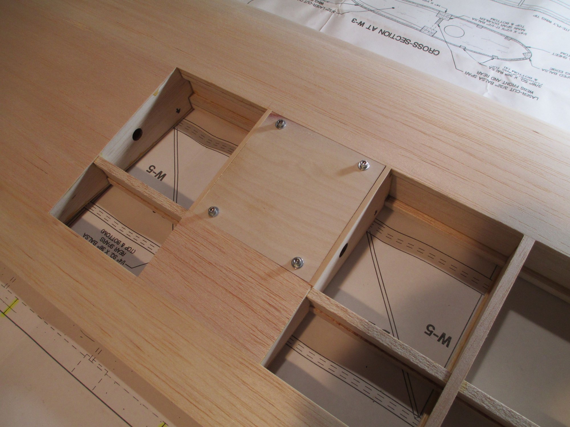
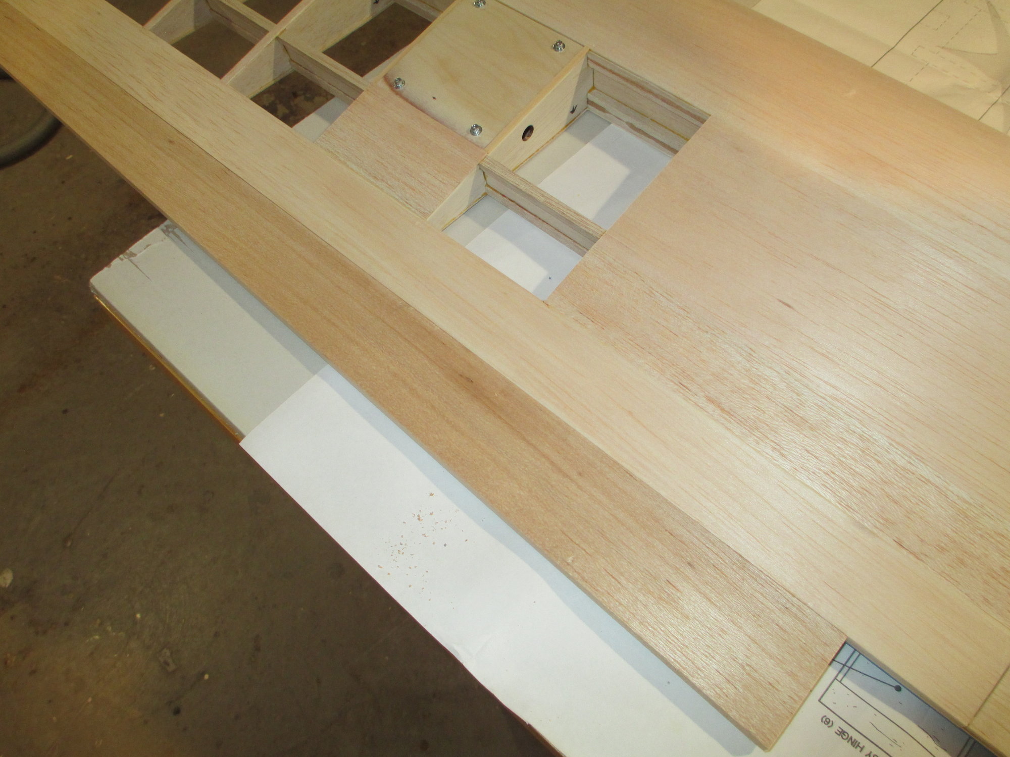
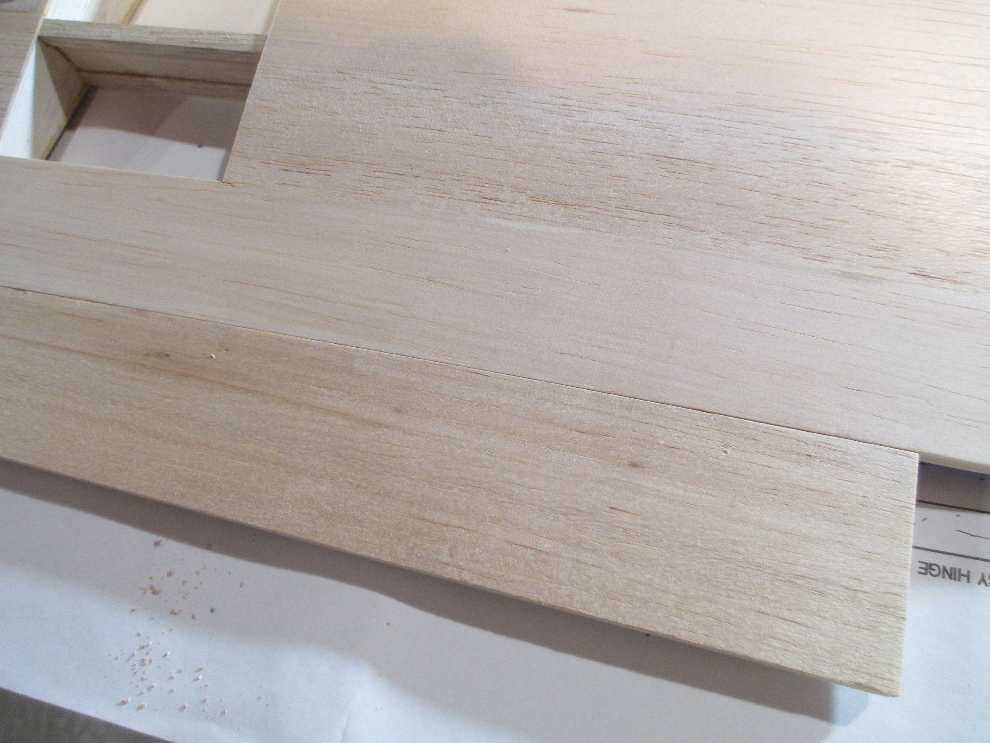
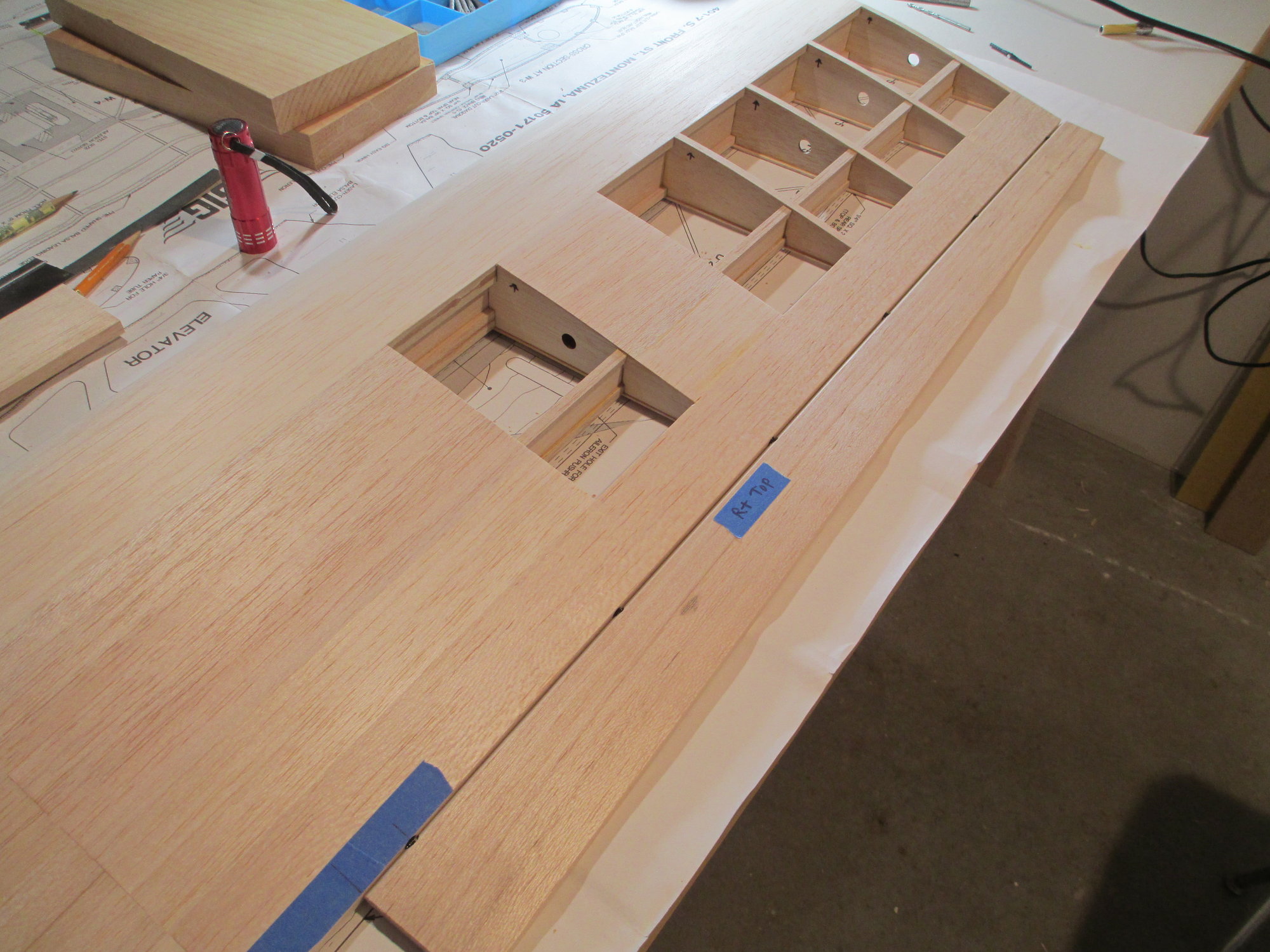
These are two brackets made from Basswood. They will hold the aileron servo cover to the wing. Each bracket is made from 1/2" x 1/8" stock epoxied together forming a 90 degree angle. I further reinforced it by gluing in a short length of Balsa tri-stock for good measure.
The brackets are epoxied to the sides of the front and rear spars. Four 4-40 cap head screws will secure the cover in place.
Last edited by VincentJ; 03-19-2019 at 02:34 AM.
The following users liked this post:
Wully (12-21-2021)
03-19-2019, 04:01 PM
#31
Thread Starter
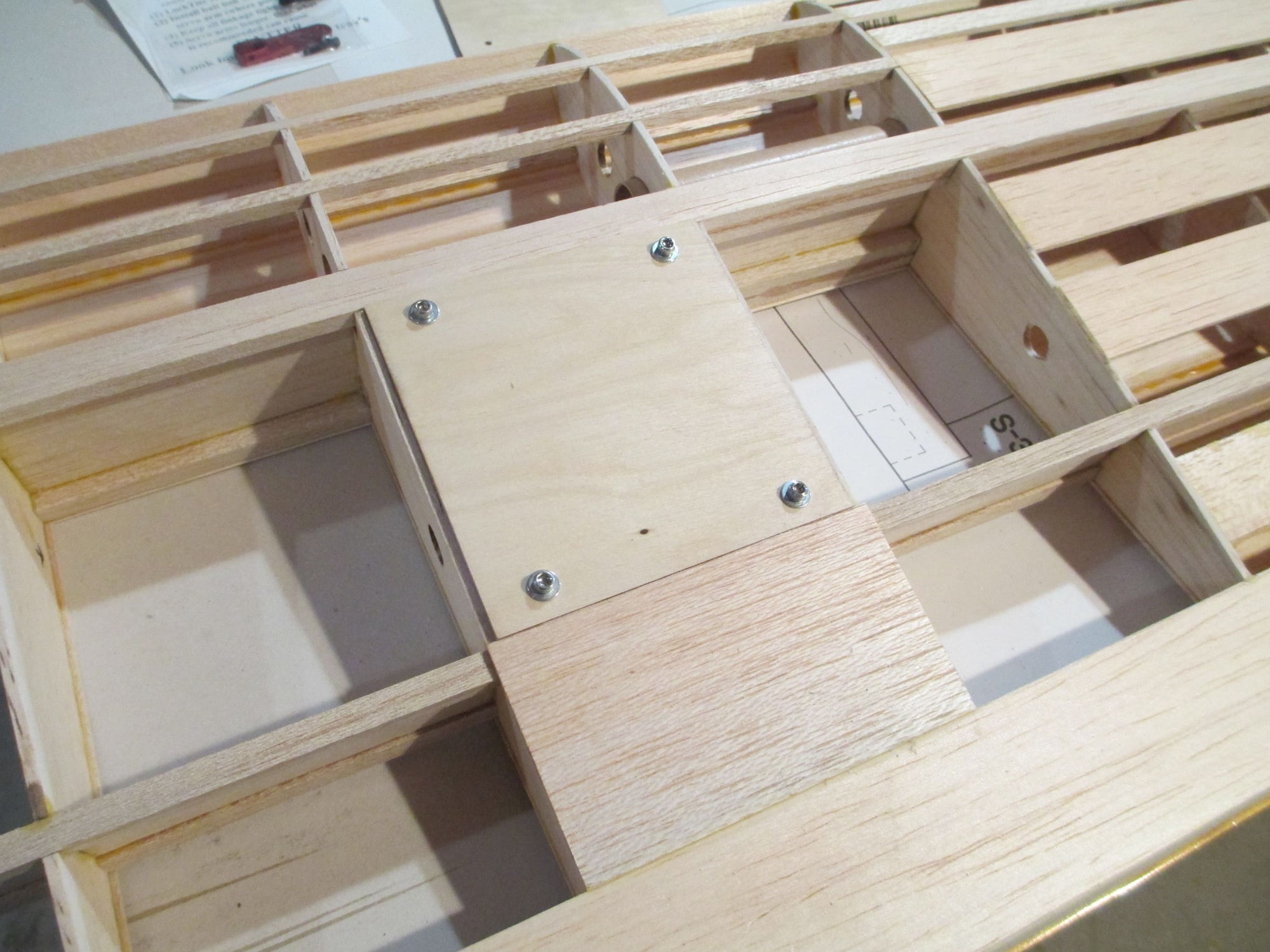
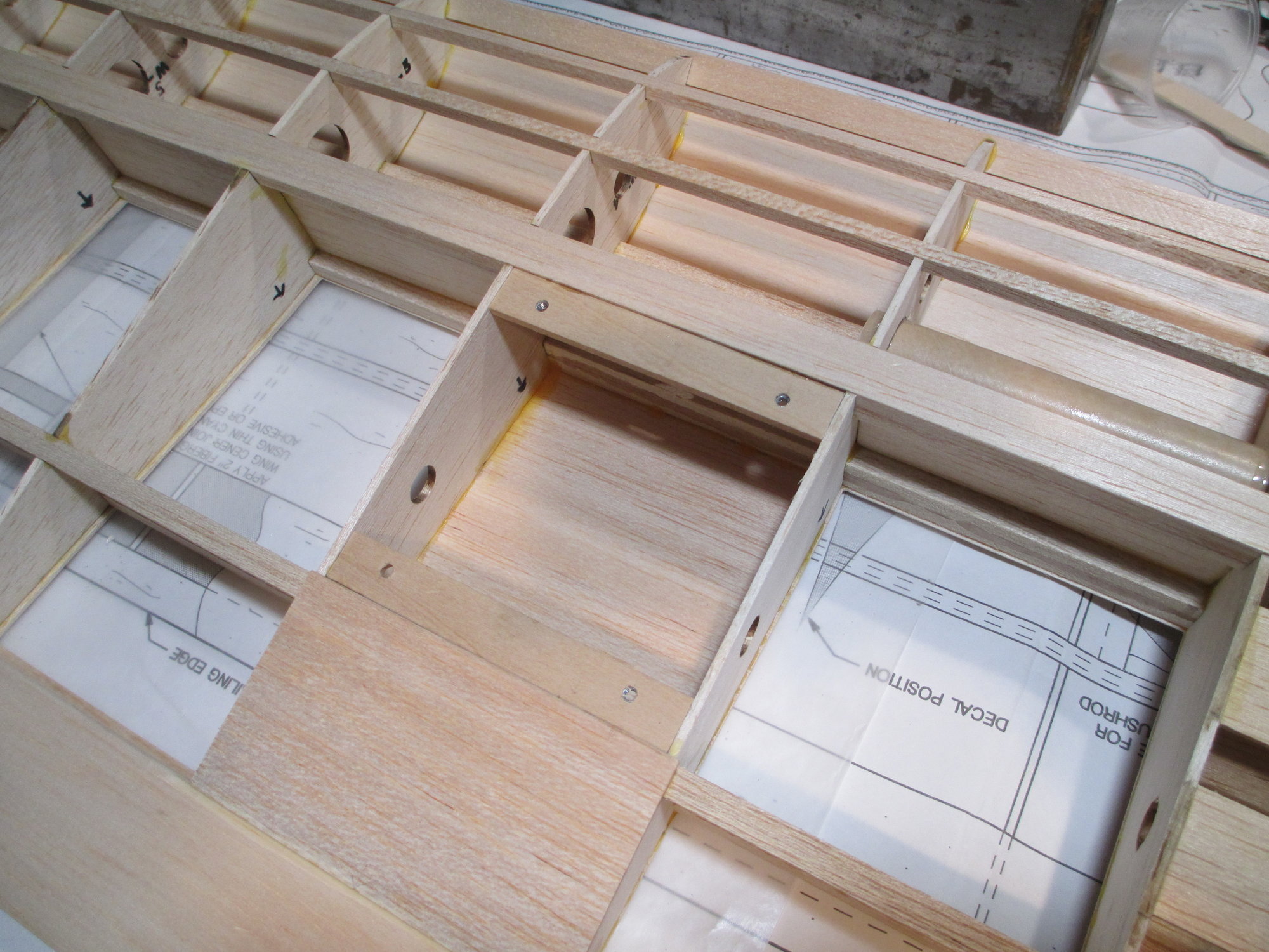
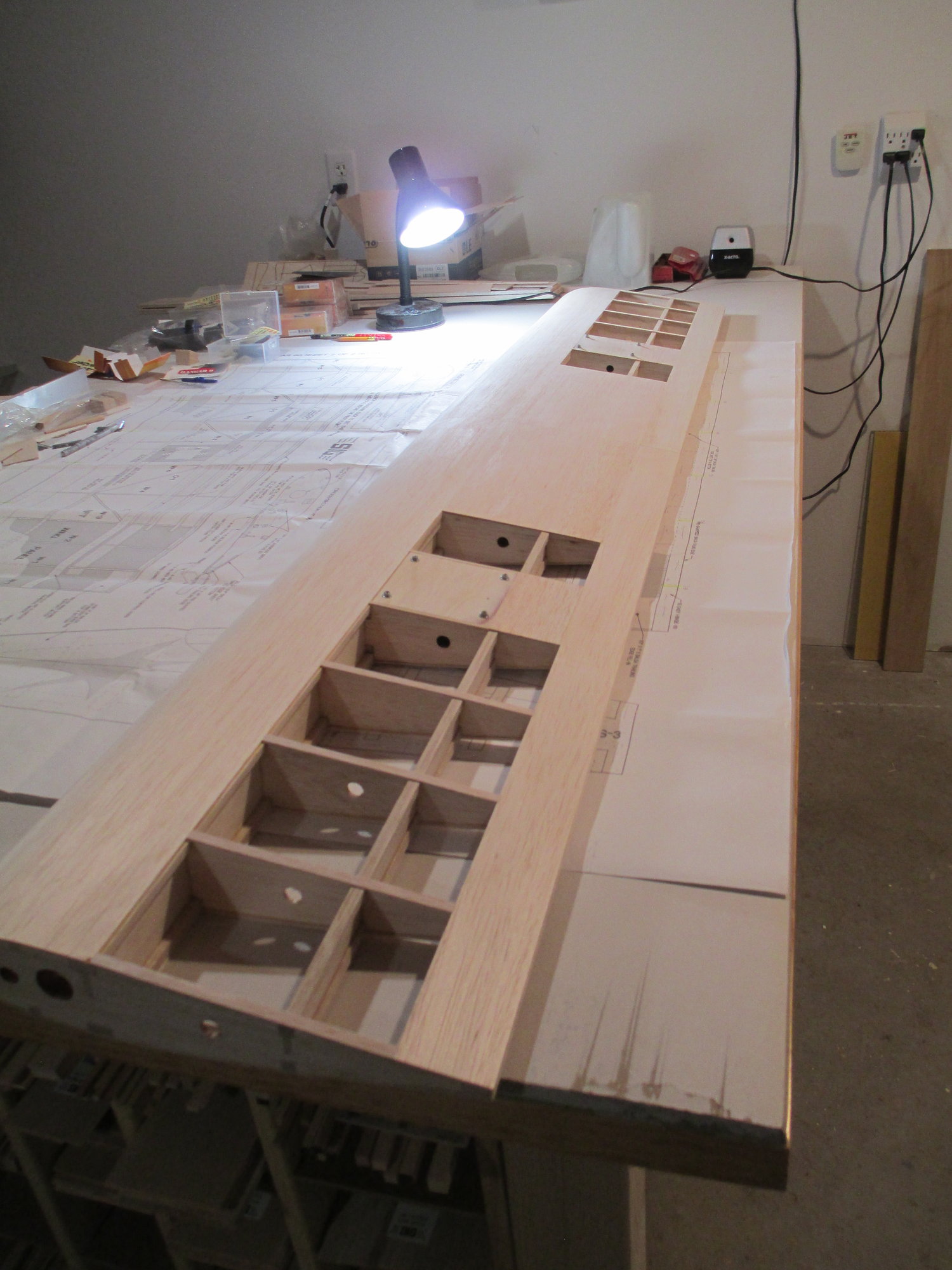
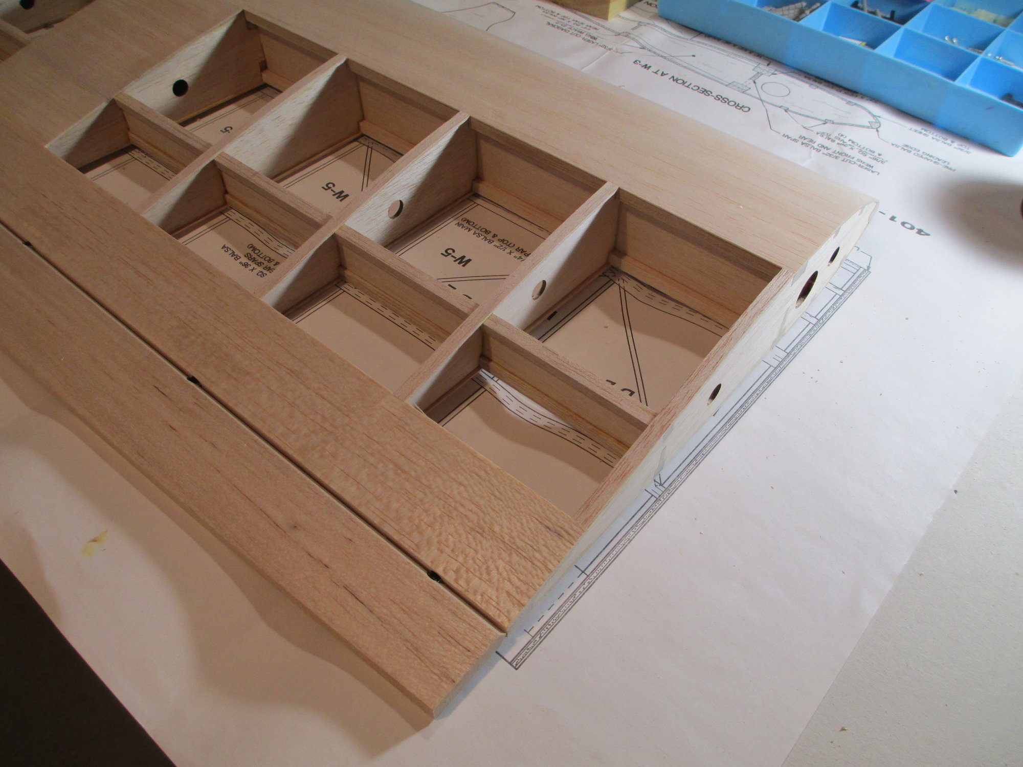
With the brackets (that I made yesterday) now in place, the servo hatch covers were fitted and secured using four 4-40 cap head screws.
Initial layout of servo placement. I'm using 5" Hangar 9 Titanium Pro-Links to connect the servo arm to the horn of the aileron.
Tomorrow I'll start sheeting the bottom half of the wing!
Last edited by VincentJ; 03-20-2019 at 04:48 AM.
The following users liked this post:
Wully (12-21-2021)
 03-21-2019, 12:26 AM
#33
Thread Starter
https://www.horizonhobby.com/titaniu...-3-(2)-han3553
Last edited by VincentJ; 03-21-2019 at 12:28 AM.
The following users liked this post:
Wully (12-21-2021)
03-22-2019, 03:33 AM
#34
Thread Starter
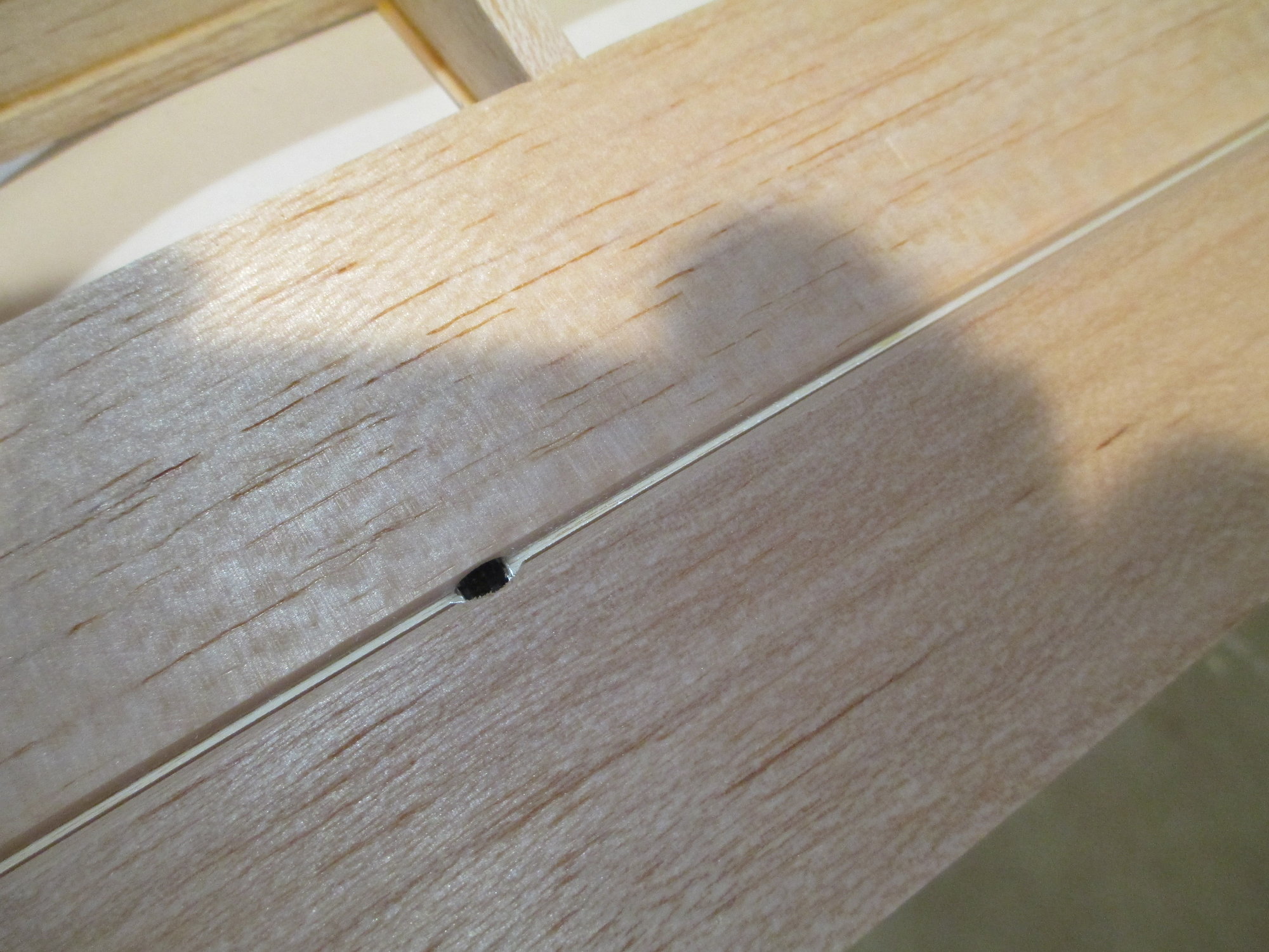
Tim, after re-reading your initial question about the part in the middle of the pushrod I may have misunderstood your question. The square part in the middle is not adjustable, it is just a spot to turn the entire turnbuckle (Pro-Link). They have a special tool (see link below) that fits on that adjuster, but a small adjustable wrench works equally as well. When you rotate the center, the entire turnbuckle will lengthen or shorten depending on which direction it's rotated.
https://www.towerhobbies.com/cgi-bin...?&I=LXHVKR&P=7
https://www.towerhobbies.com/cgi-bin...?&I=LXHVKR&P=7
Last edited by VincentJ; 03-22-2019 at 03:39 AM.
The following users liked this post:
Wully (12-21-2021)
03-22-2019, 08:05 AM
#35
That makes more sense. I wondered how that little thing could join two rods and keep the whole thing solid, but assumed it must. I get it's just there to give a tool something to grab onto to turn the entire length of the solid rod. Thanks for the clearing that up.
The following users liked this post:
Wully (12-21-2021)
03-22-2019, 03:21 PM
#36
Thread Starter
Sheeting of the wing continues. As the glue is drying, thought I'd finish up the servo mounts...
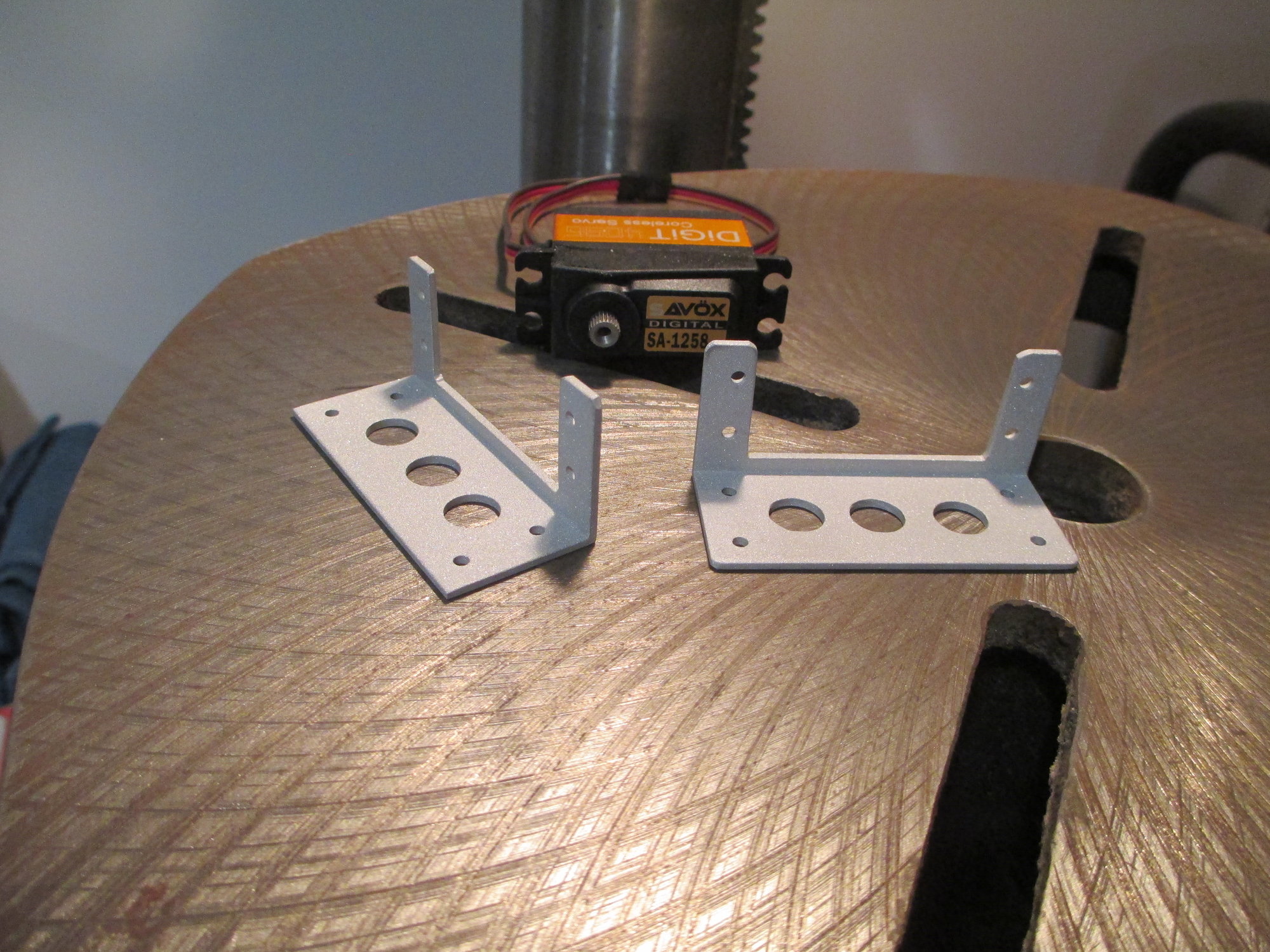
Finished product...
No, I didn't paint them. This is what aluminum looks like after glass beading them.
Finished product...
No, I didn't paint them. This is what aluminum looks like after glass beading them.
Last edited by VincentJ; 03-22-2019 at 11:15 PM.
The following users liked this post:
Wully (12-21-2021)
The following users liked this post:
Wully (12-21-2021)
03-22-2019, 05:36 PM
#38
Not to beleaguer the subject of the turnbuckle control rods, I like the looks of them and will get some, but with no jam nuts what keeps the threads from unscrewing under the effects of vibration? Is it a really tight fit on the threads?
The following users liked this post:
Wully (12-21-2021)
03-22-2019, 11:21 PM
#39
Thread Starter
I'm using 1-1/4" half arms with 4-40 tap made by SWB. Since I'm using Savox servos which have 25 splines on the output shaft, the arms used are for Futaba.
http://www.swbmfg.com/futaba-aluminu...pped-for-4-40/
Last edited by VincentJ; 03-22-2019 at 11:36 PM.
03-22-2019, 11:52 PM
#40
Thread Starter
https://www.dubro.com/collections/ba...uty-ball-links
03-23-2019, 04:28 PM
#41
Thread Starter
Sheeting is done! I'm ready to hinge the ailerons next...
Each servo cover will have to later be resized to give clearance for the covering.
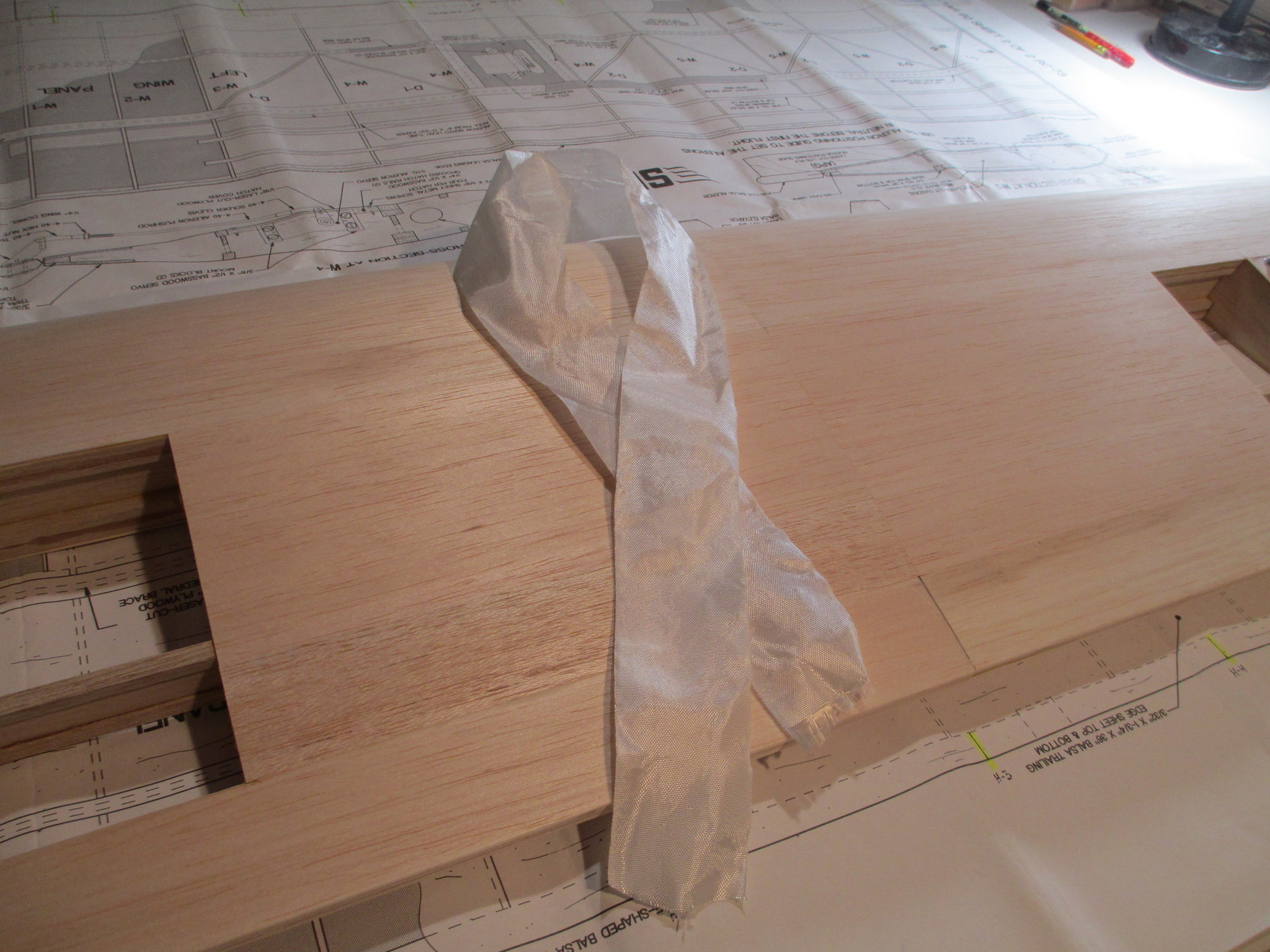
This is the 2" wide fiberglass strip (supplied in the kit) that will get wrapped around the wing's center seam. This is a step that should not be overlooked as this will prevent the wing from splitting in two... I like to use finishing resin to secure it into place.
Each servo cover will have to later be resized to give clearance for the covering.
This is the 2" wide fiberglass strip (supplied in the kit) that will get wrapped around the wing's center seam. This is a step that should not be overlooked as this will prevent the wing from splitting in two... I like to use finishing resin to secure it into place.
Last edited by VincentJ; 03-24-2019 at 12:08 AM.
The following users liked this post:
Wully (12-21-2021)
03-24-2019, 05:55 AM
#42
Thread Starter
Part One - How To Install Robart Hinge Points
Don't be intimidated by using these type of hinges on your project. It's easier than you think, you can do it!!!
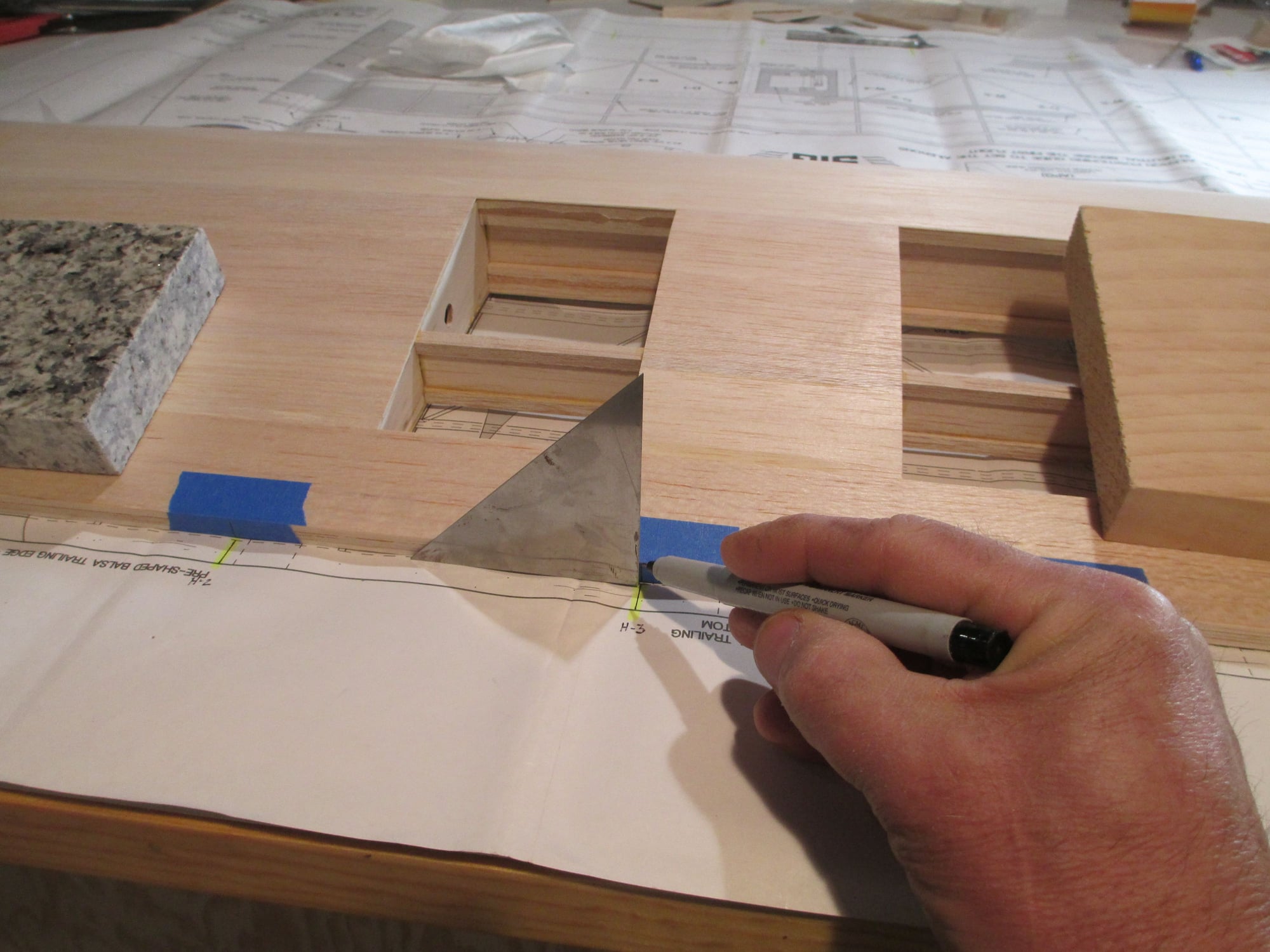
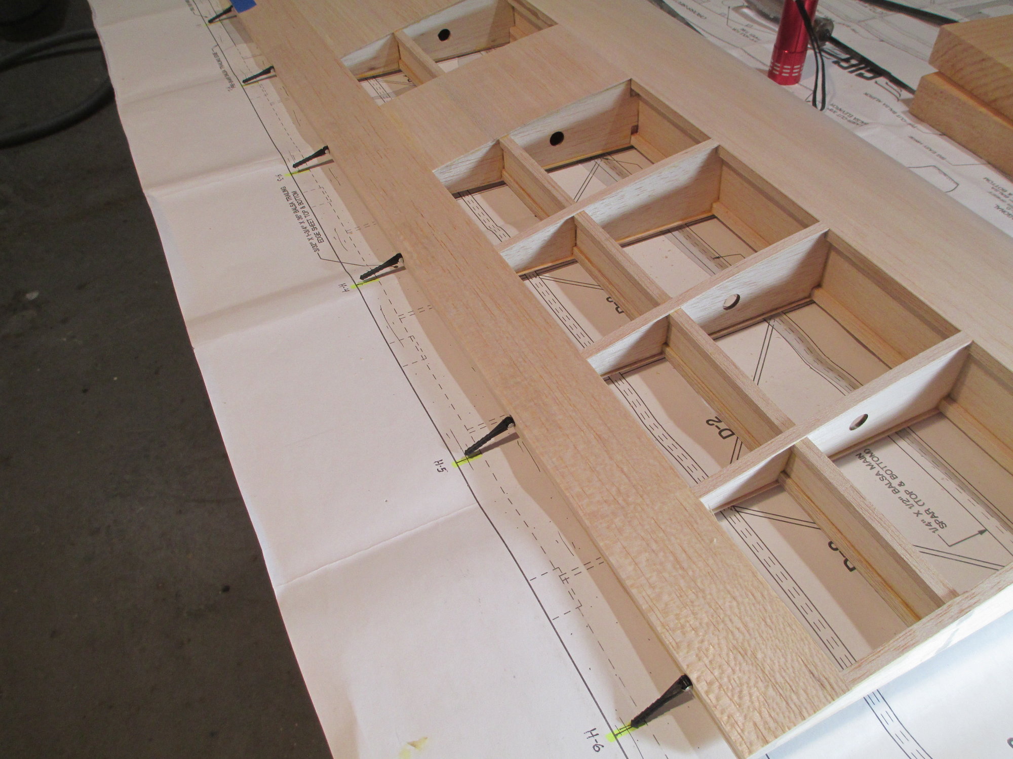
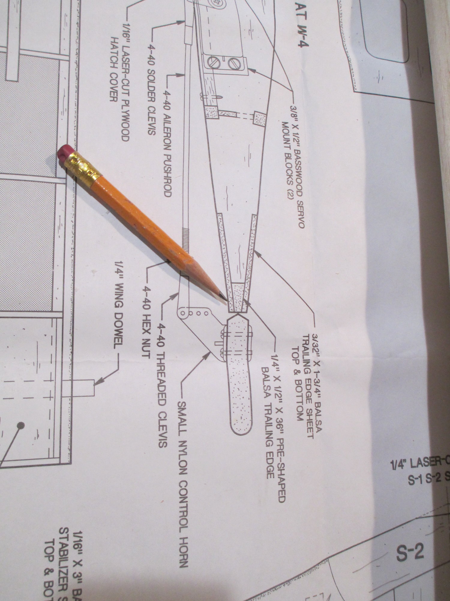
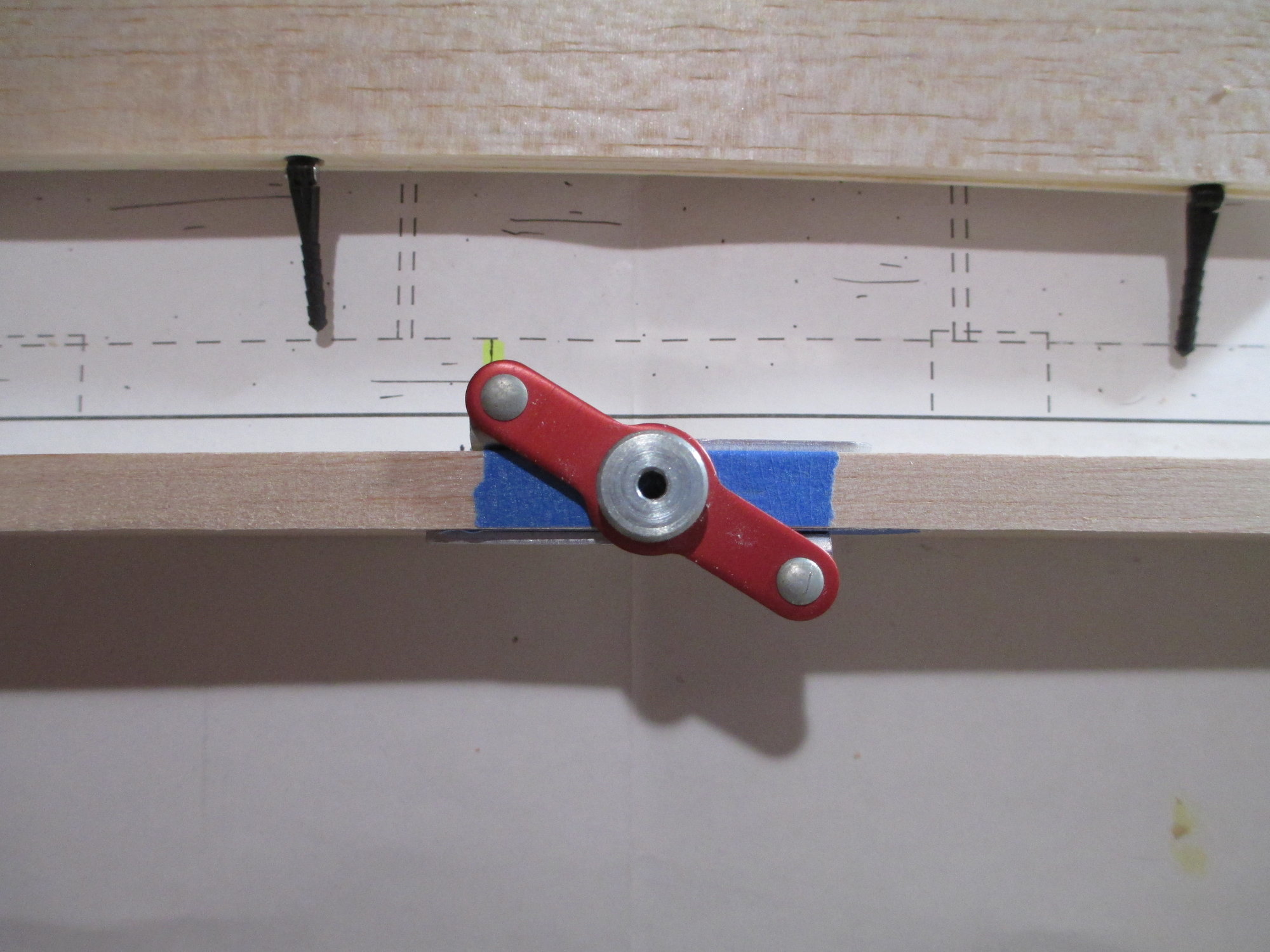
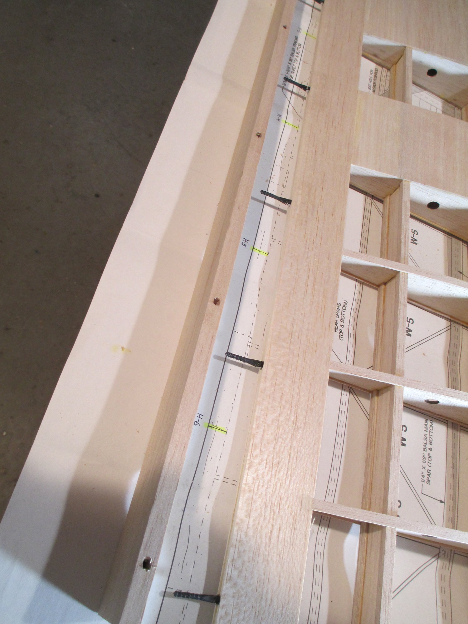
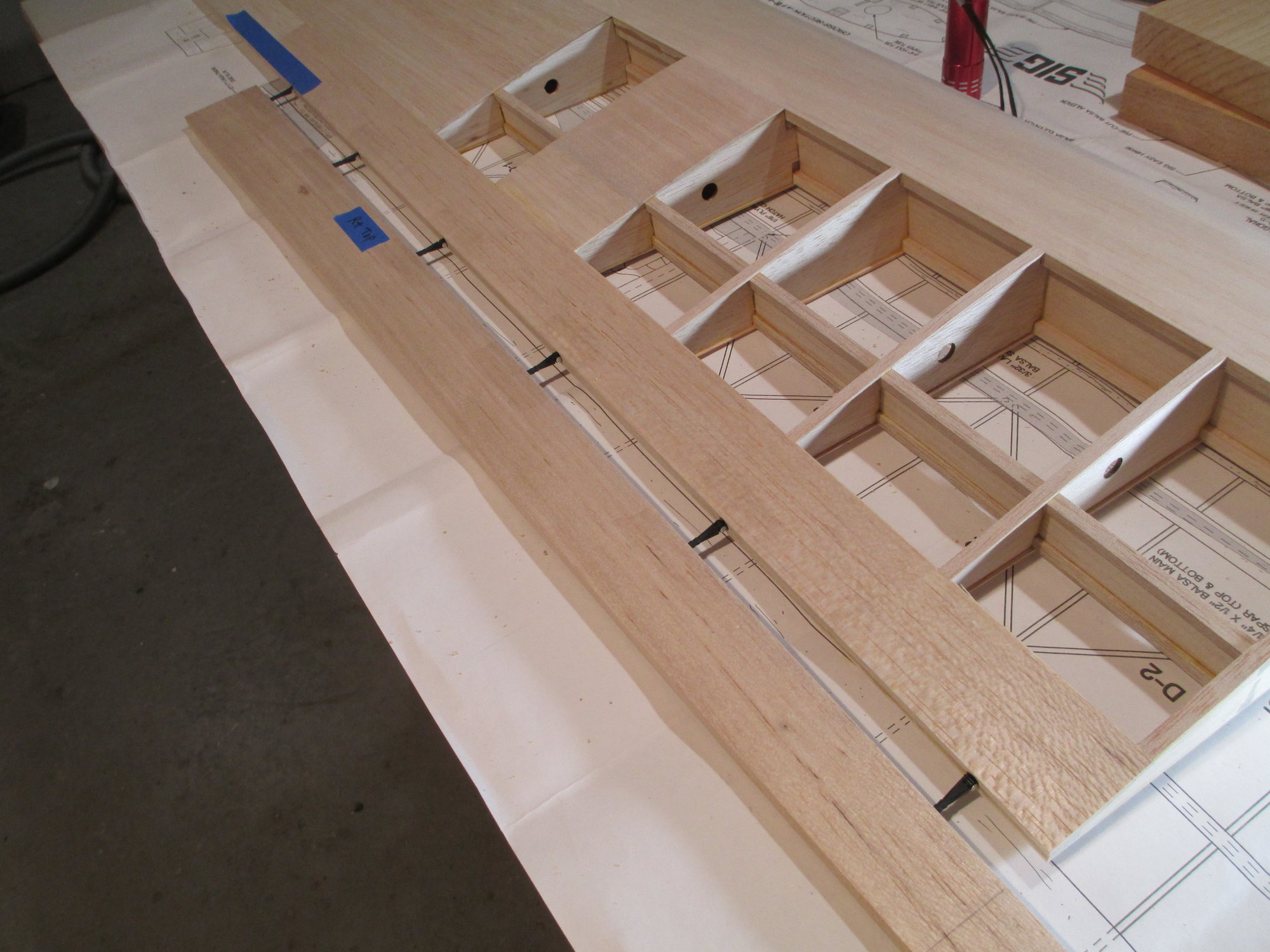
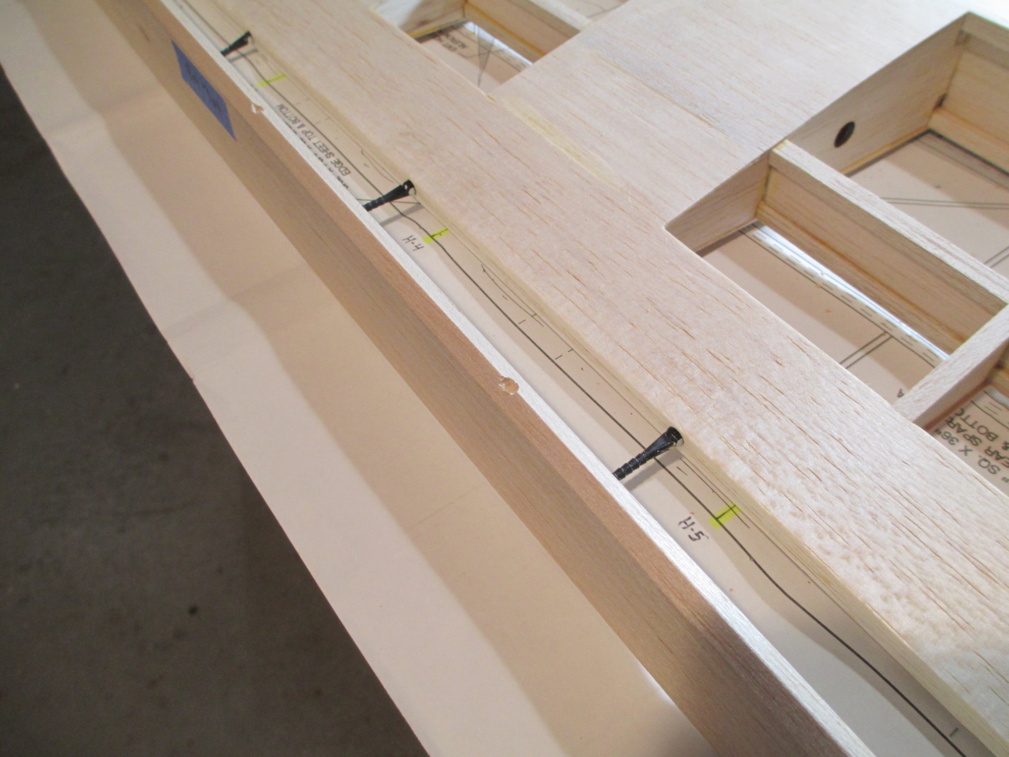
I first start the process by marking the exact locations of the hinges from the plans to the TE of the wing. Notice that I have first placed blue painters tape on the wing.
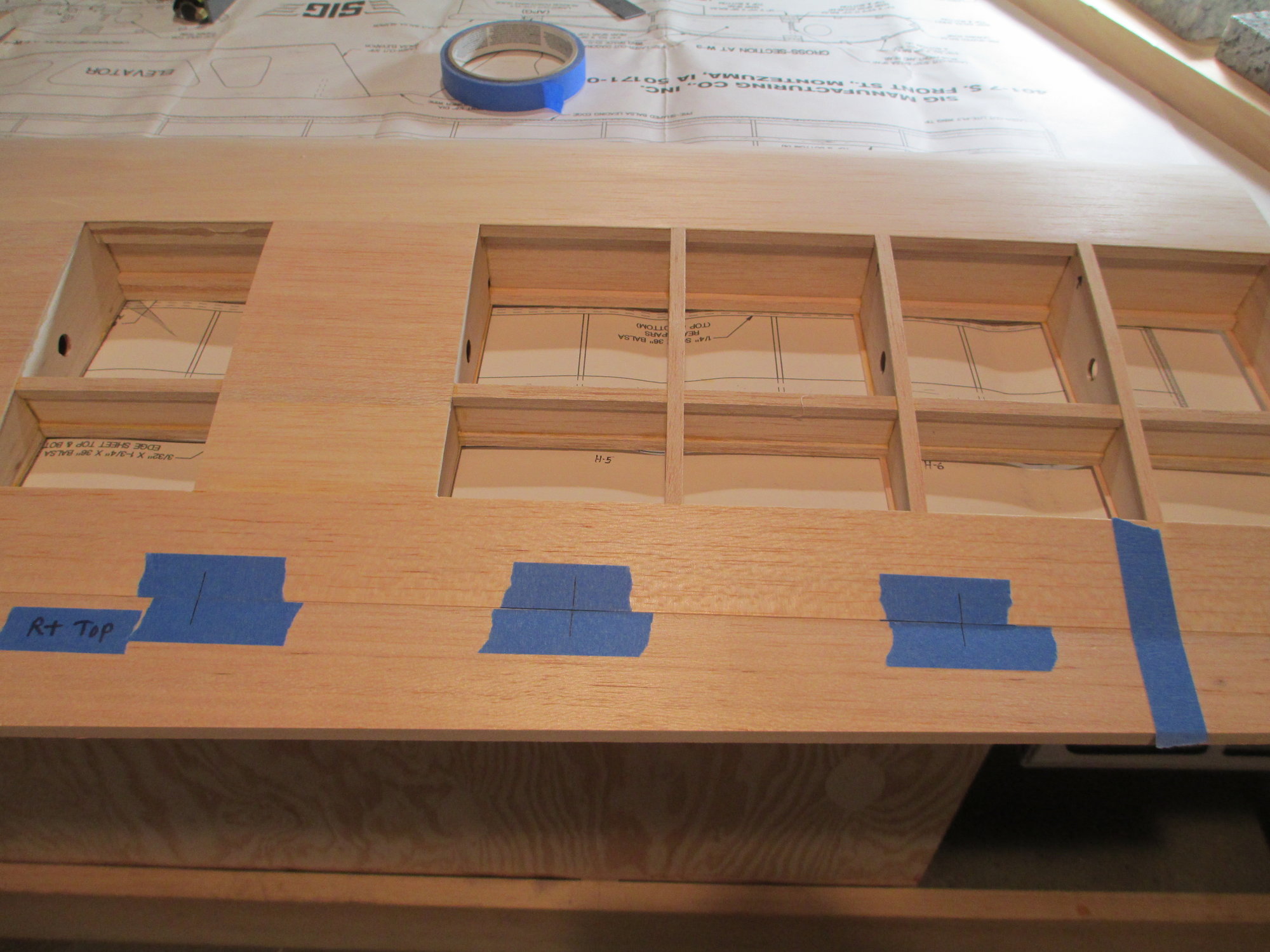
The aileron is taped against the TE and the hinge marks are also transferred to the top of the aileron.
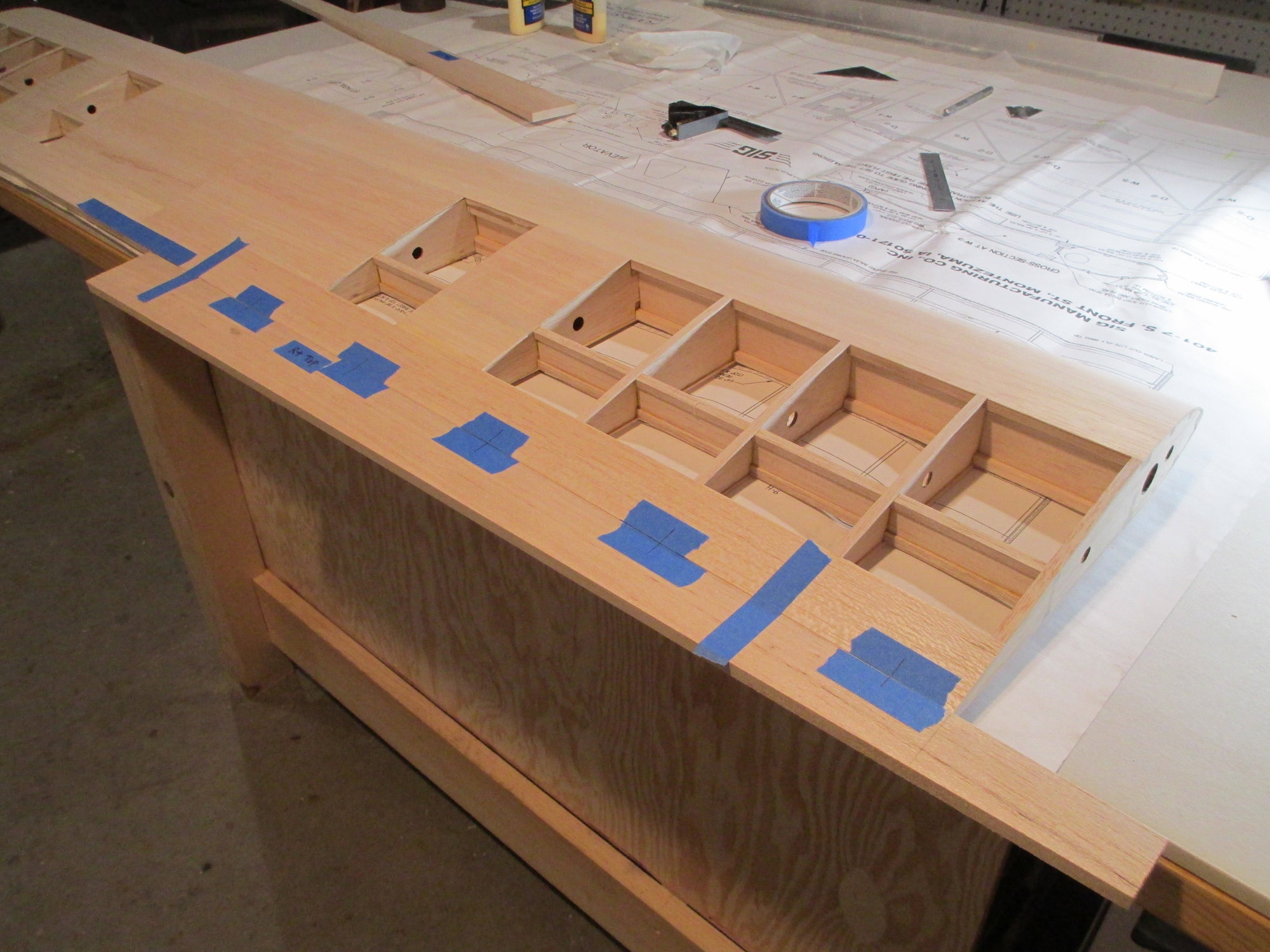
There are a total of six hinges per aileron. Note the excess aileron extending beyond the wing panel. I will trim this off after the hinging process is completed.
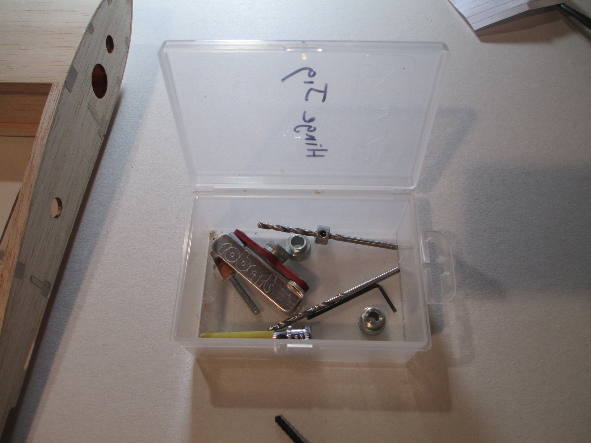
I keep all, or most of what I need to make hinges in a small kit that I assembled. This saves me time having to look for what I need!
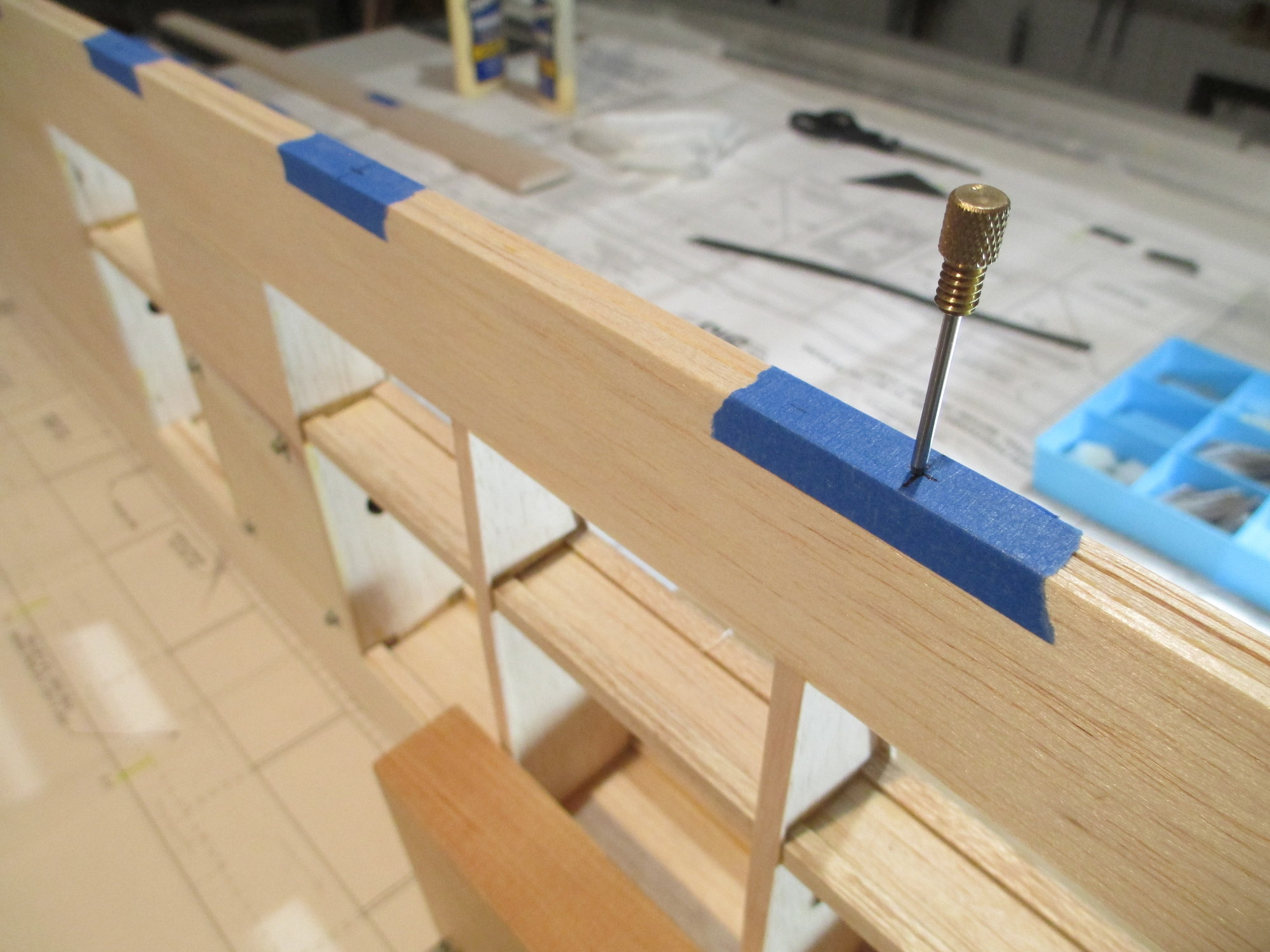
Divide the thickness of the TE of the wing and mark the exact spot of where to drill. I'm using the small scribe tool that is usually found on your square...that is if you haven't already lost it!
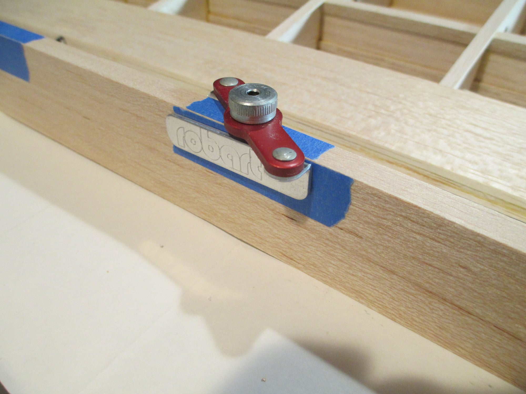
I like to use the hinge drill jig made by Robart. I find that using an awl to locate the indentation that I had previously made is the best way to locate the jig in the exact position.
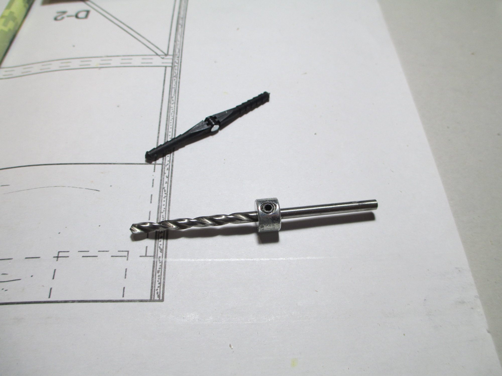
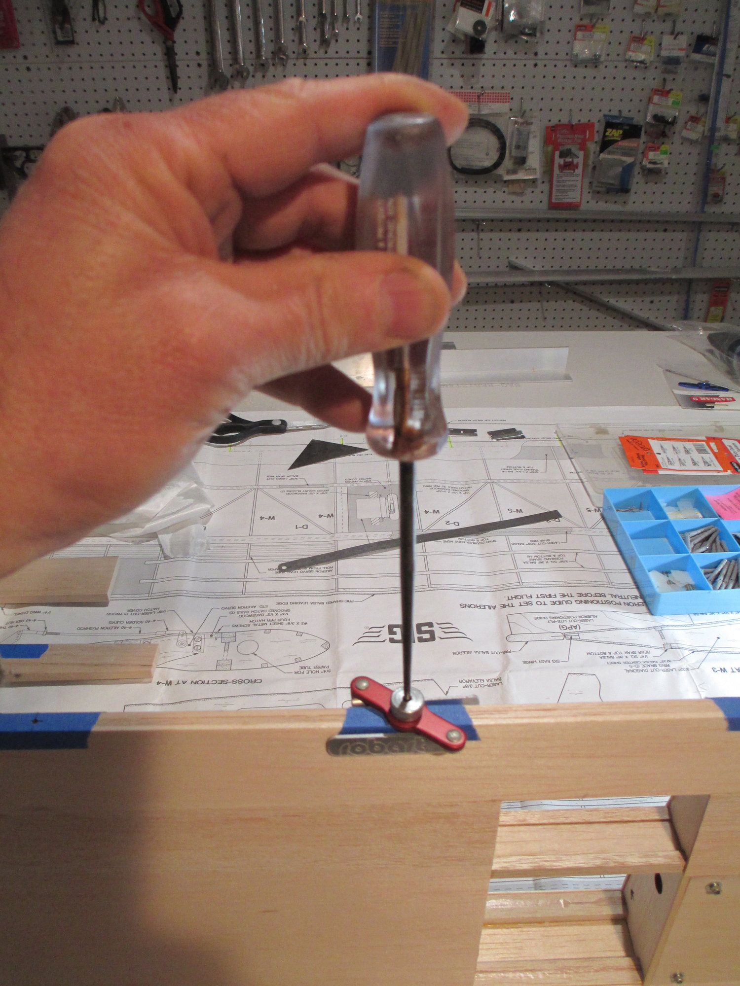
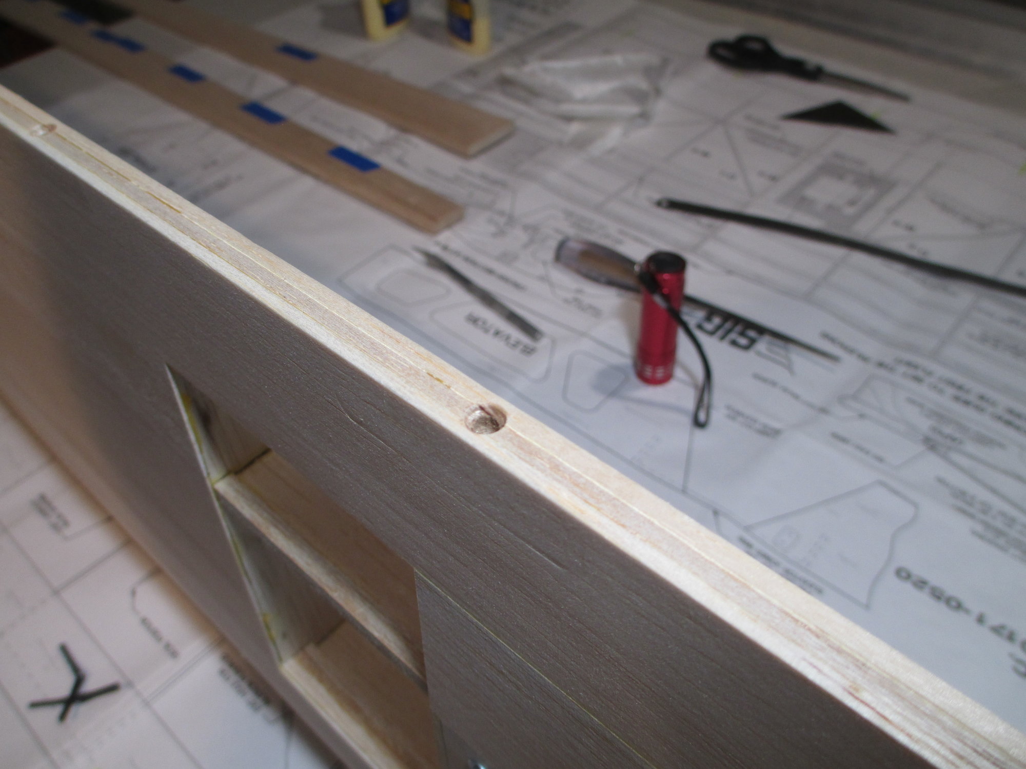
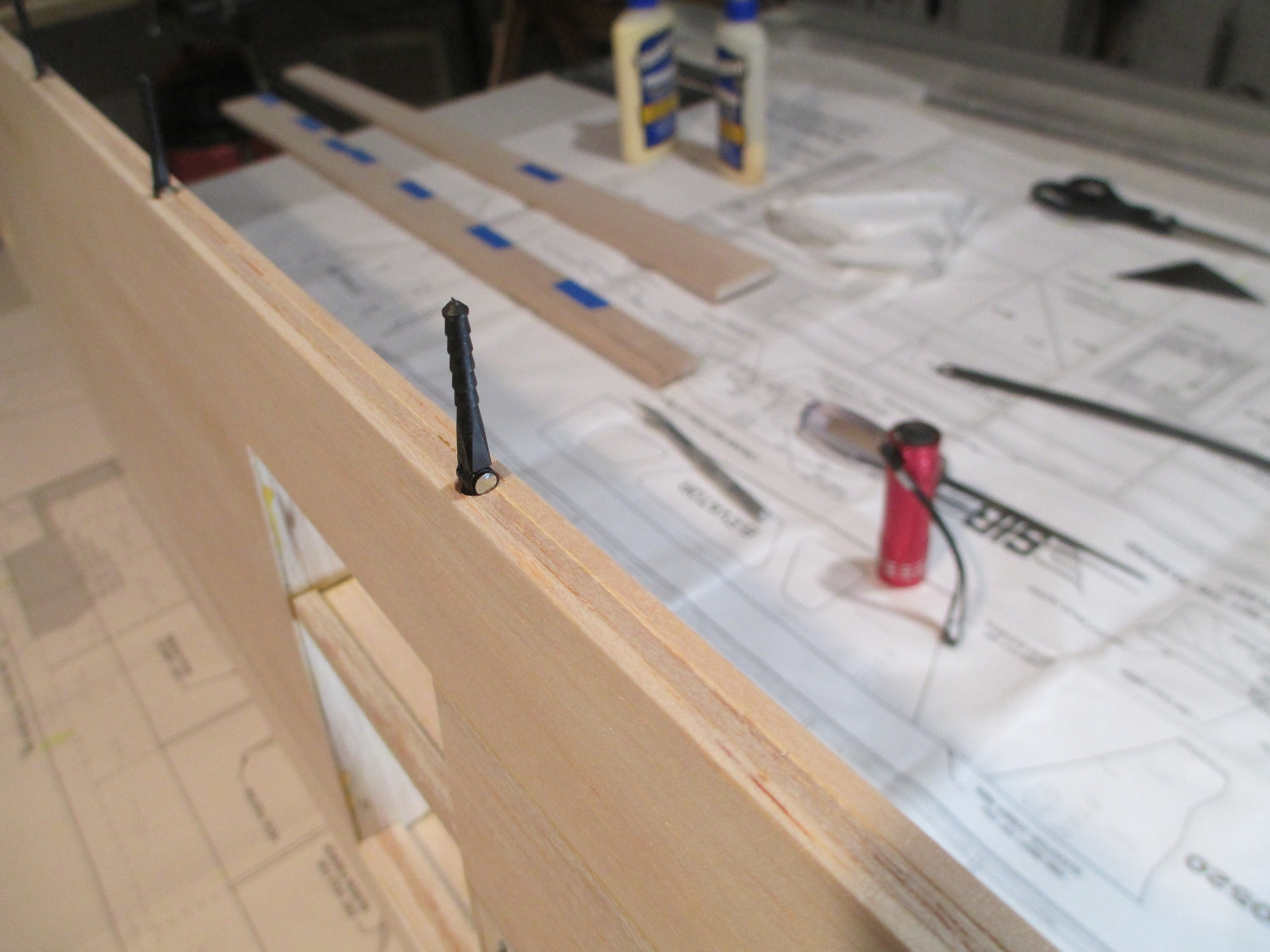
Since I'm using 1/8" hinges I'm using a sharp 1/8" drill bit. I found at my local hardware store these depth stops for different size drill bits. I have it adjusted to the depth that I want.
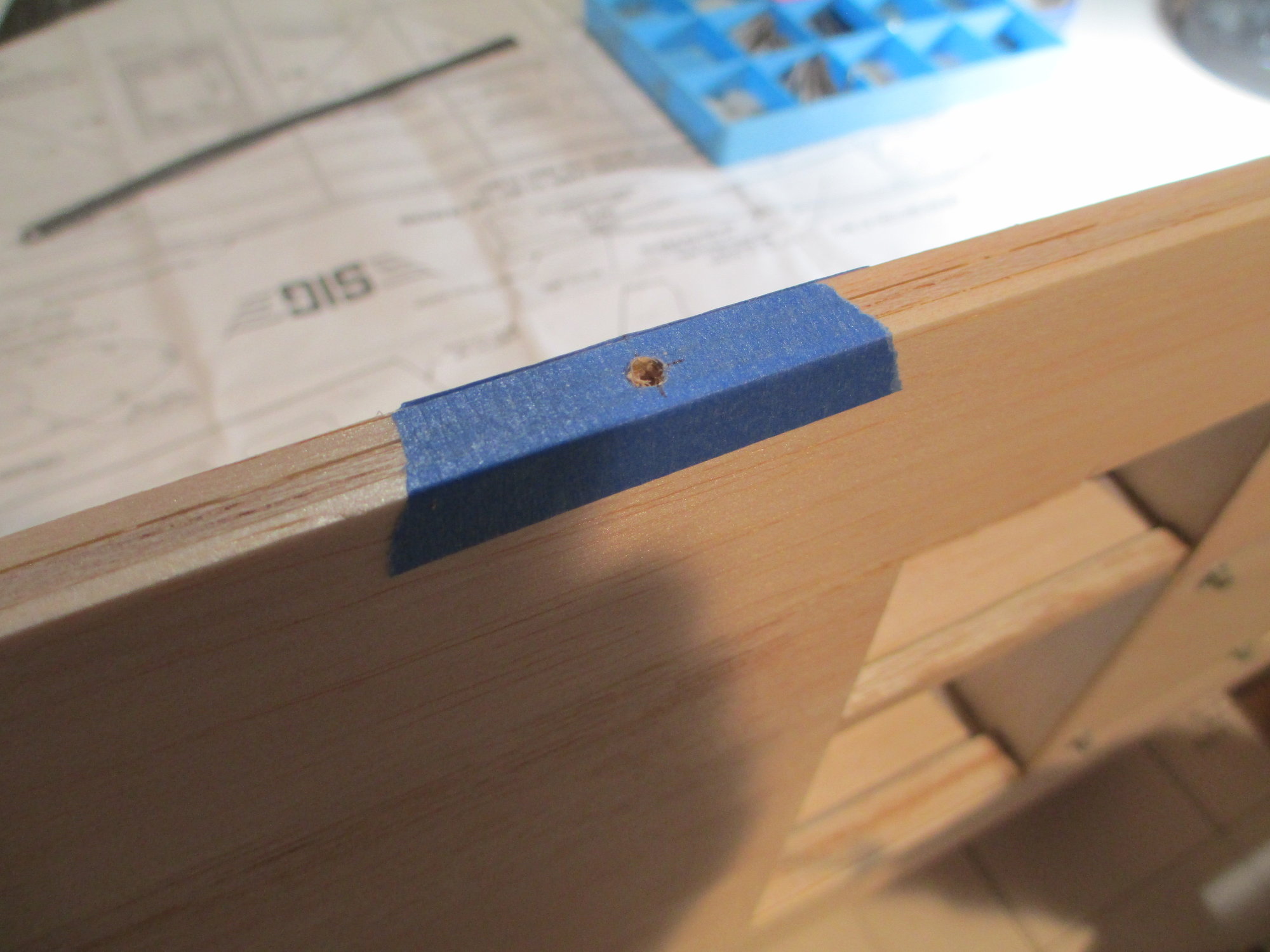
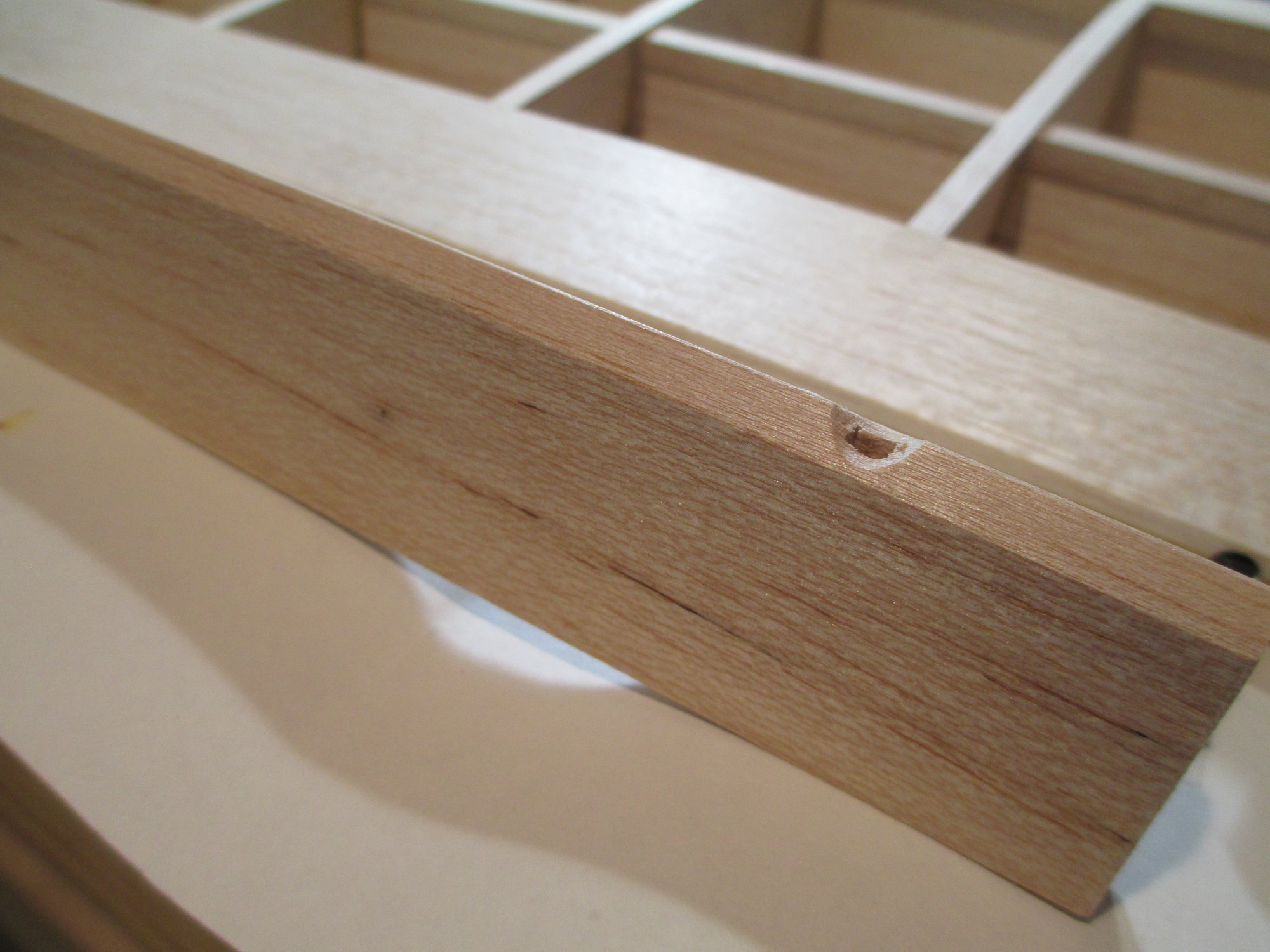
This is what is should look like after drilling (step #1) is done.
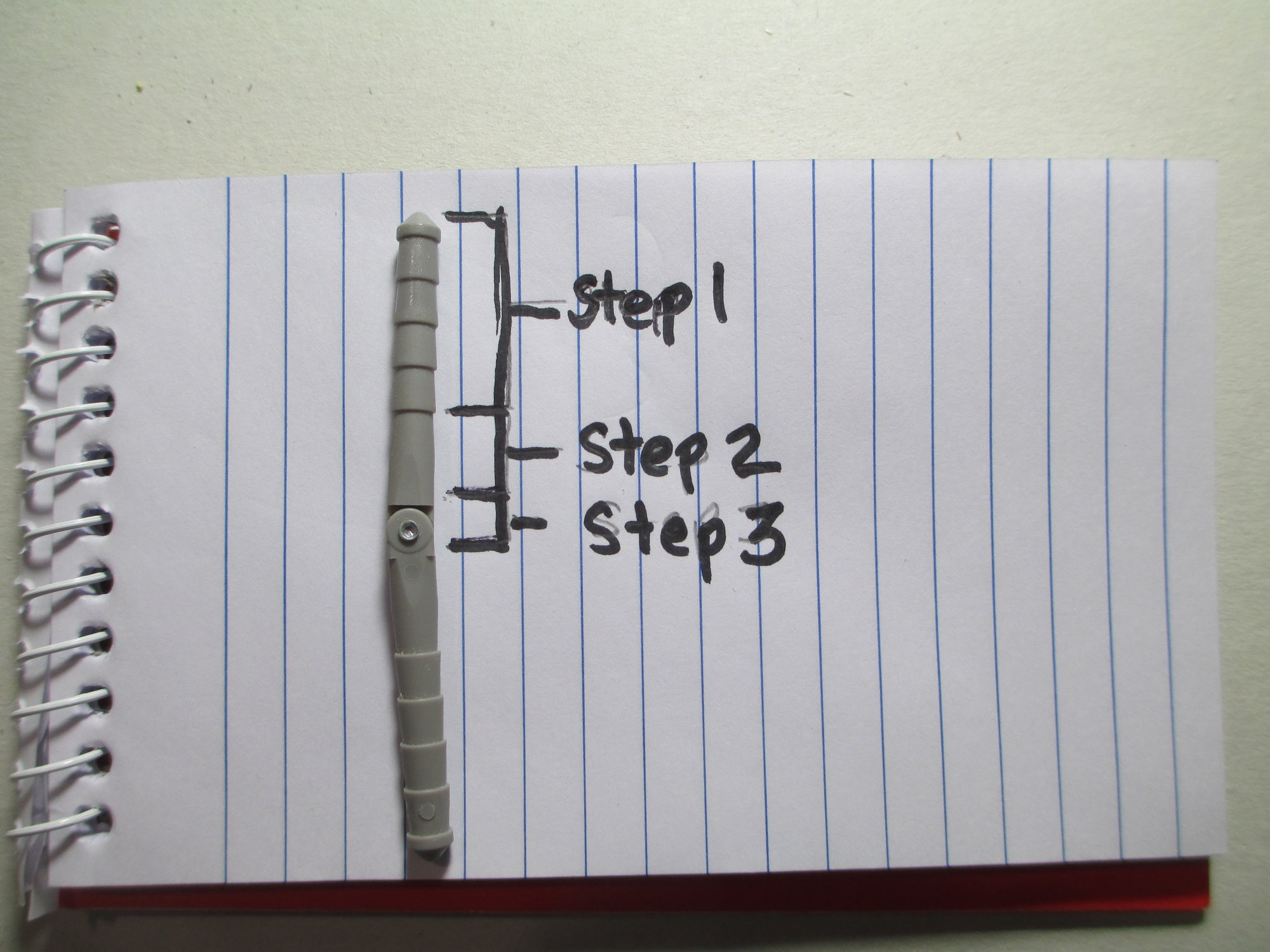
In order for your hinges to fit properly, you will have to accommodate for the three parts of the hinge. Step #1 is the the through hole using a 1/8" bit. Step #2 is to taper the hole to fit the tapered part of the hinge. I use a tapered grinding stone bit on my Dremel tool for this. Step #3 is to enlarge to top of the hole using a different stone bit to accommodate the knuckle of the hinge. (I will take pics of these stone bits and post in Part #2 of hinging.)
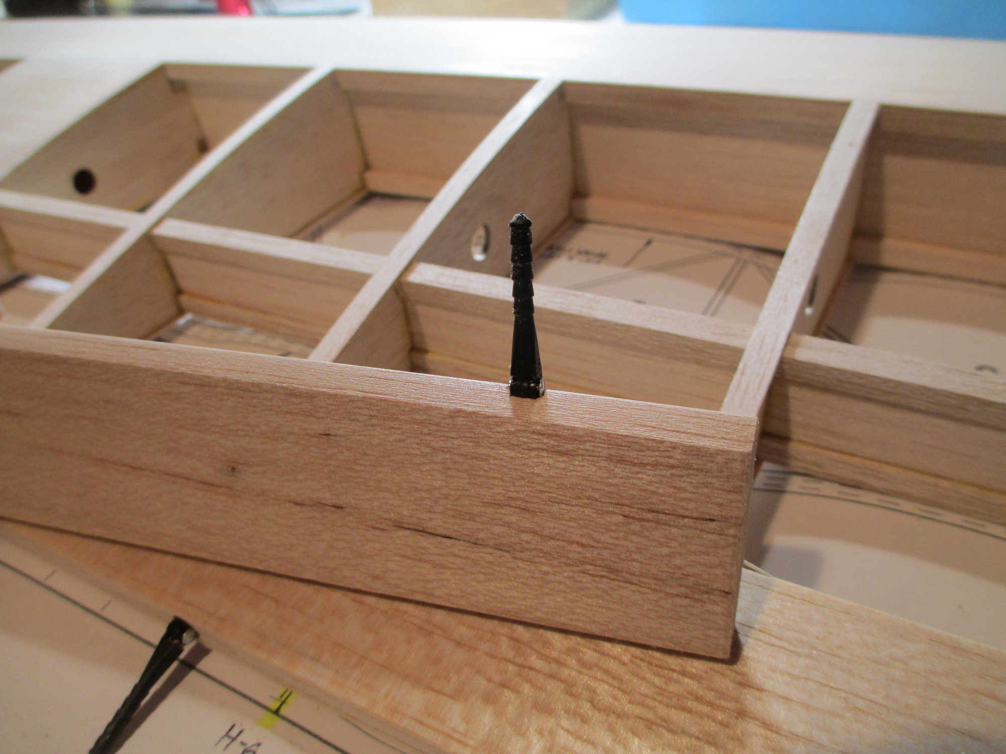
This is what it now should look like after doing all three steps.
Each hinge is fitting perfectly.
Don't be intimidated by using these type of hinges on your project. It's easier than you think, you can do it!!!
I first start the process by marking the exact locations of the hinges from the plans to the TE of the wing. Notice that I have first placed blue painters tape on the wing.
The aileron is taped against the TE and the hinge marks are also transferred to the top of the aileron.
There are a total of six hinges per aileron. Note the excess aileron extending beyond the wing panel. I will trim this off after the hinging process is completed.
I keep all, or most of what I need to make hinges in a small kit that I assembled. This saves me time having to look for what I need!
Divide the thickness of the TE of the wing and mark the exact spot of where to drill. I'm using the small scribe tool that is usually found on your square...that is if you haven't already lost it!
I like to use the hinge drill jig made by Robart. I find that using an awl to locate the indentation that I had previously made is the best way to locate the jig in the exact position.
Since I'm using 1/8" hinges I'm using a sharp 1/8" drill bit. I found at my local hardware store these depth stops for different size drill bits. I have it adjusted to the depth that I want.
This is what is should look like after drilling (step #1) is done.
In order for your hinges to fit properly, you will have to accommodate for the three parts of the hinge. Step #1 is the the through hole using a 1/8" bit. Step #2 is to taper the hole to fit the tapered part of the hinge. I use a tapered grinding stone bit on my Dremel tool for this. Step #3 is to enlarge to top of the hole using a different stone bit to accommodate the knuckle of the hinge. (I will take pics of these stone bits and post in Part #2 of hinging.)
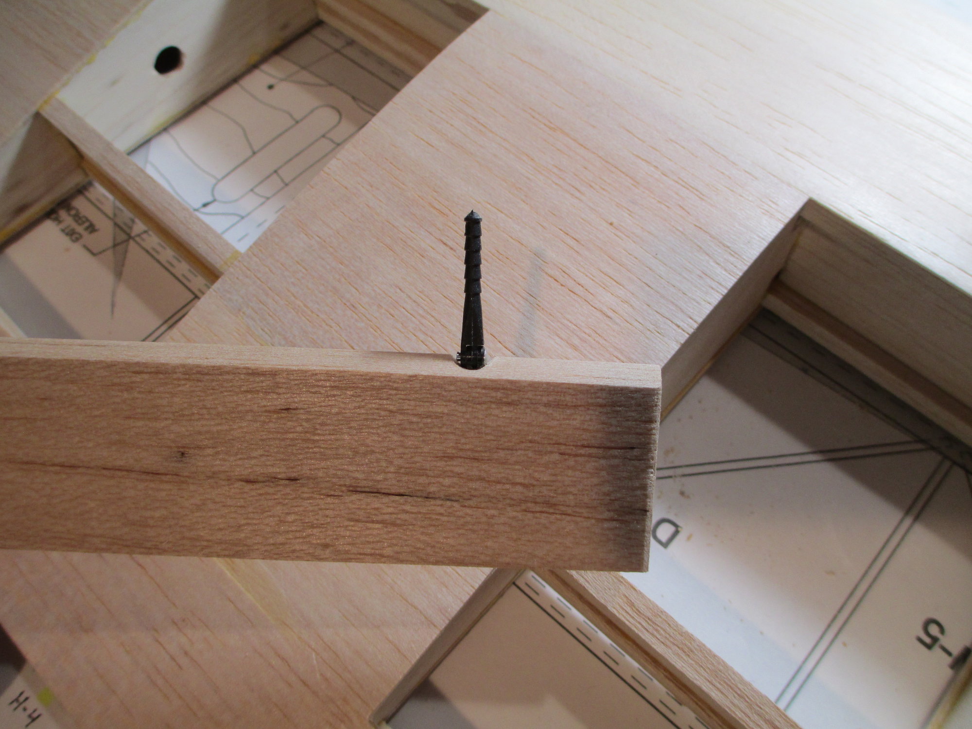
This is what it now should look like after doing all three steps.
Each hinge is fitting perfectly.
Last edited by VincentJ; 03-25-2019 at 04:45 AM.
The following users liked this post:
Wully (12-21-2021)
The following users liked this post:
Wully (12-21-2021)
03-24-2019, 11:39 AM
#44
Thread Starter
Part Two - How To Install Robart Hinge Points
The pencil pointing to the LE of the aileron shows that it's beveled at 45 degrees.
When drilling the 1/8" hinge holes in the aileron, it's to your benefit not to bevel the LE of the aileron. Leave it square, and get the drilling done first. The jig will make better contact with a top flat increasing your chances for a perfectly placed hole.
Using the drill jig on flat stock is very easy compared to the tapered TE of the wing.
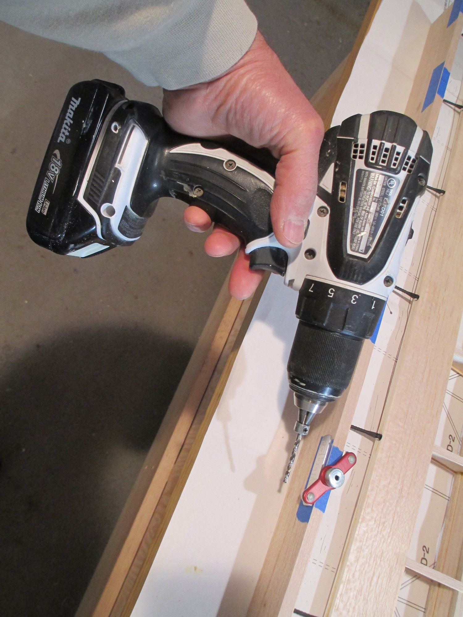
This is the cordless drill that I use. The smaller and lighter the drill, the better control you'll have. You definitely don't want to be using an electric drill here as the cord will get in your way!
Step #1 completed.
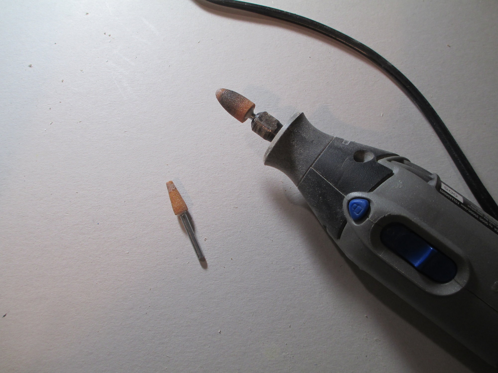
These are the two tapered grinding stone attachments for my Dremel that I use for steps 2-3. (The stone attachment that is chucked into the Dremel will perform step #3.)
Once drilled, the 2nd step of fitting the hinge into the aileron side is performed as done on the TE of the wing. (Step #3 will be done after the bevel is made.) If you measured everything precisely there should be no surprises with the fitment.
Once pressed together they should mate together seamlessly.
...and they do.
With the aileron now locked in place with the wing I can now trim off the excess aileron stock.
The pencil pointing to the LE of the aileron shows that it's beveled at 45 degrees.
When drilling the 1/8" hinge holes in the aileron, it's to your benefit not to bevel the LE of the aileron. Leave it square, and get the drilling done first. The jig will make better contact with a top flat increasing your chances for a perfectly placed hole.
Using the drill jig on flat stock is very easy compared to the tapered TE of the wing.
This is the cordless drill that I use. The smaller and lighter the drill, the better control you'll have. You definitely don't want to be using an electric drill here as the cord will get in your way!
Step #1 completed.
These are the two tapered grinding stone attachments for my Dremel that I use for steps 2-3. (The stone attachment that is chucked into the Dremel will perform step #3.)
Once drilled, the 2nd step of fitting the hinge into the aileron side is performed as done on the TE of the wing. (Step #3 will be done after the bevel is made.) If you measured everything precisely there should be no surprises with the fitment.
Once pressed together they should mate together seamlessly.
...and they do.
With the aileron now locked in place with the wing I can now trim off the excess aileron stock.
Last edited by VincentJ; 03-25-2019 at 04:50 AM.
The following users liked this post:
Wully (12-21-2021)
03-24-2019, 03:02 PM
#45
Thread Starter
Part Three - How To Install Robart Hinge Points
This is the 3rd, and final tutorial on installing Robart hinges. Sorry for being so long winded, but I hope that you find this information helpful.
After completing steps 1 & 2 (but not #3) on the aileron, now is the time to create the 45 degree beveled edge. Here I have the aileron clamped into place.
With the bevel completed it's time to perform step #3, creating clearance for the knuckle. Note how the center of the bevel falls directly over each hinge hole.
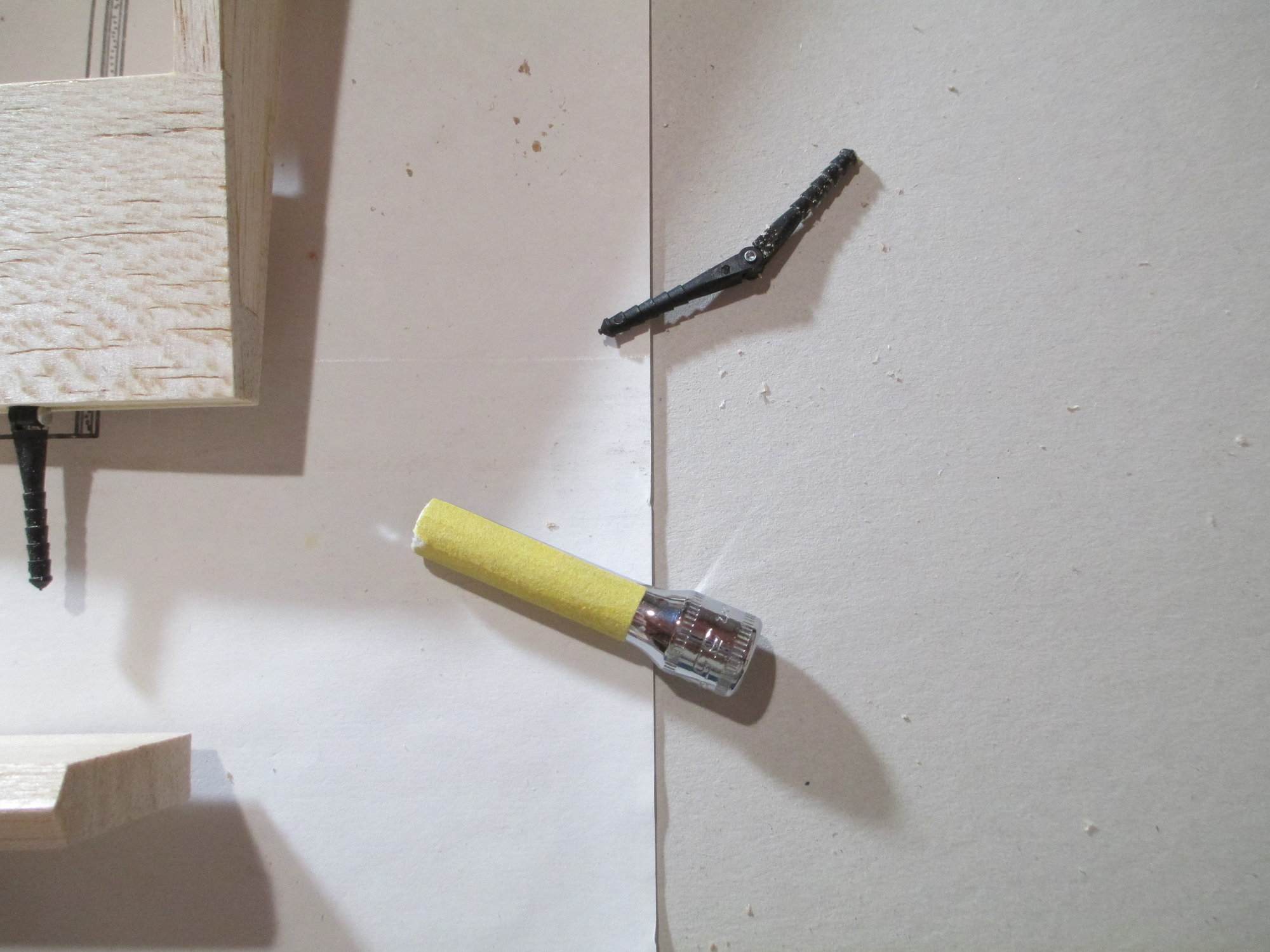
This is what I use. Simply stick a piece of 220 grit sandpaper on a deep socket.
Position the socket directly over each hinge point hole and slowly sand the bevel to create the space for the knuckle. This is what it should look like.
Sorry, this pic is out of sequence. In this photo the hinge is installed in its hole after completing step #2, but before the 3rd step.
Looks about right.
Time to see if it fits.
I barely have any hinge gap, that's a good thing.
This is what it should look like completed. Now you can see the notch made with the socket.
It's time to fit each aileron servo on their respective hatches.
This is the 3rd, and final tutorial on installing Robart hinges. Sorry for being so long winded, but I hope that you find this information helpful.
After completing steps 1 & 2 (but not #3) on the aileron, now is the time to create the 45 degree beveled edge. Here I have the aileron clamped into place.
With the bevel completed it's time to perform step #3, creating clearance for the knuckle. Note how the center of the bevel falls directly over each hinge hole.
This is what I use. Simply stick a piece of 220 grit sandpaper on a deep socket.
Position the socket directly over each hinge point hole and slowly sand the bevel to create the space for the knuckle. This is what it should look like.
Sorry, this pic is out of sequence. In this photo the hinge is installed in its hole after completing step #2, but before the 3rd step.
Looks about right.
Time to see if it fits.
I barely have any hinge gap, that's a good thing.
This is what it should look like completed. Now you can see the notch made with the socket.
It's time to fit each aileron servo on their respective hatches.
Last edited by VincentJ; 03-25-2019 at 02:51 AM.
The following 2 users liked this post by VincentJ:
Superdutyspinner (05-02-2024),
Wully (12-21-2021)


The following users liked this post:
Wully (12-21-2021)

The following users liked this post:
Wully (12-21-2021)
The following users liked this post:
Wully (12-21-2021)
03-25-2019, 12:31 AM
#49
Thread Starter
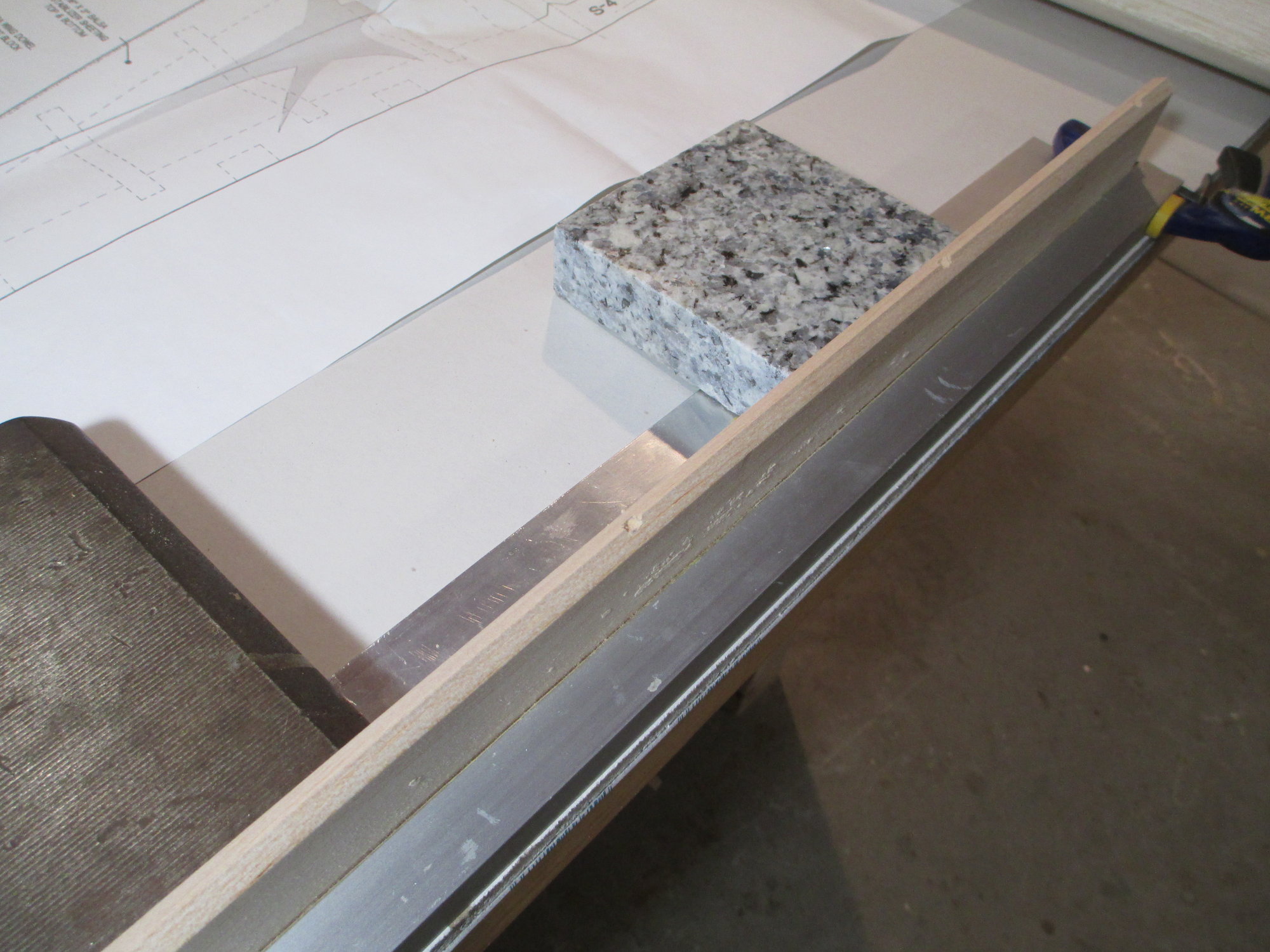
If I were to taper such a piece, there are several ways to do it, some requiring jigs to make sure that you end up with a uniform taper/thickness. But I think I would opt for just using my trusty hand plane to get it to where I want it, then just finish it up with one of my long sanding bars...
03-25-2019, 03:31 PM
#50
Thread Starter
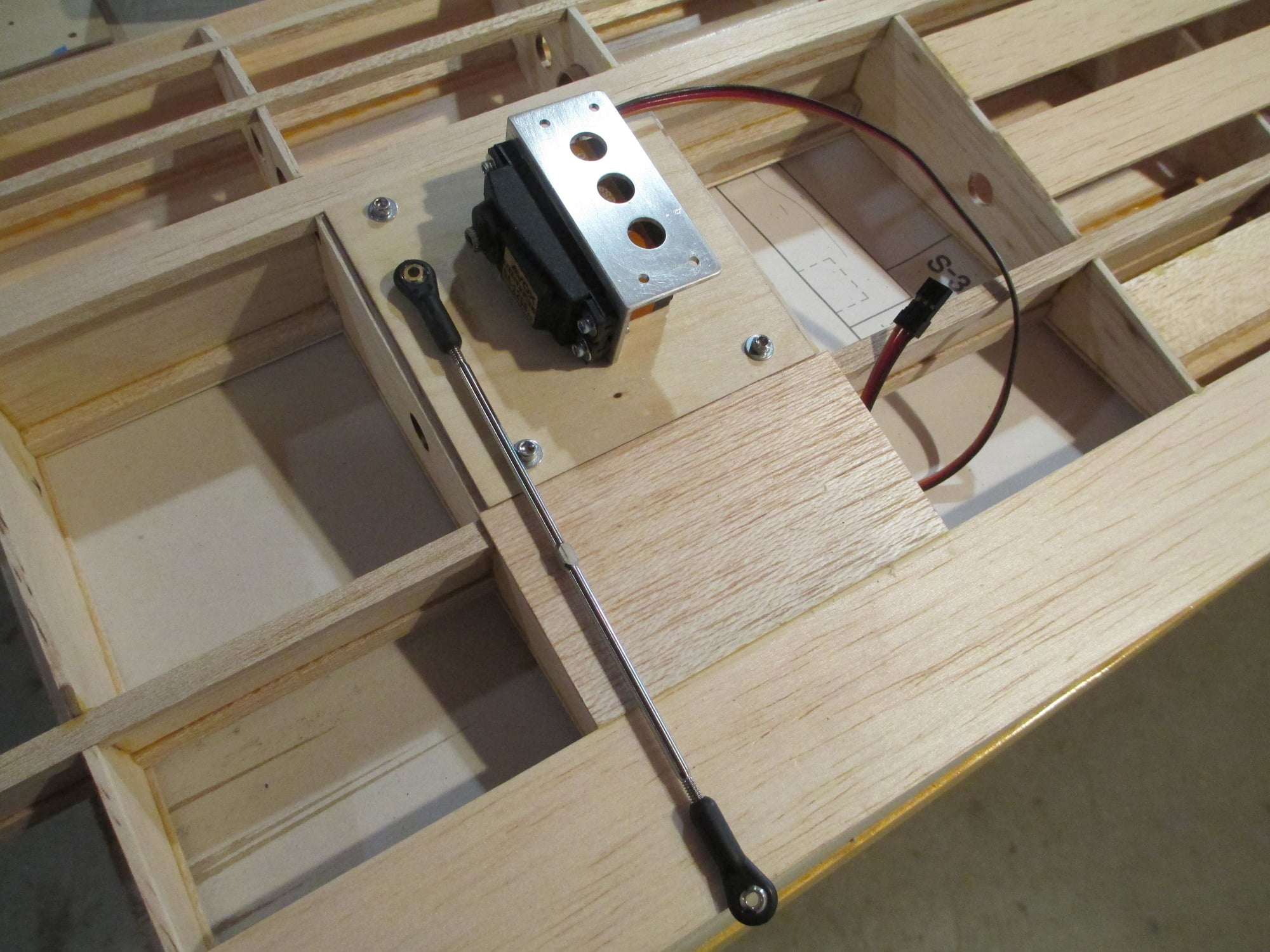
Tonight's task was to get the servos mounted. It's pretty clear now to see how all the pieces come together; the aluminum mount, the servo and hatch cover. I love it when a plan comes together!
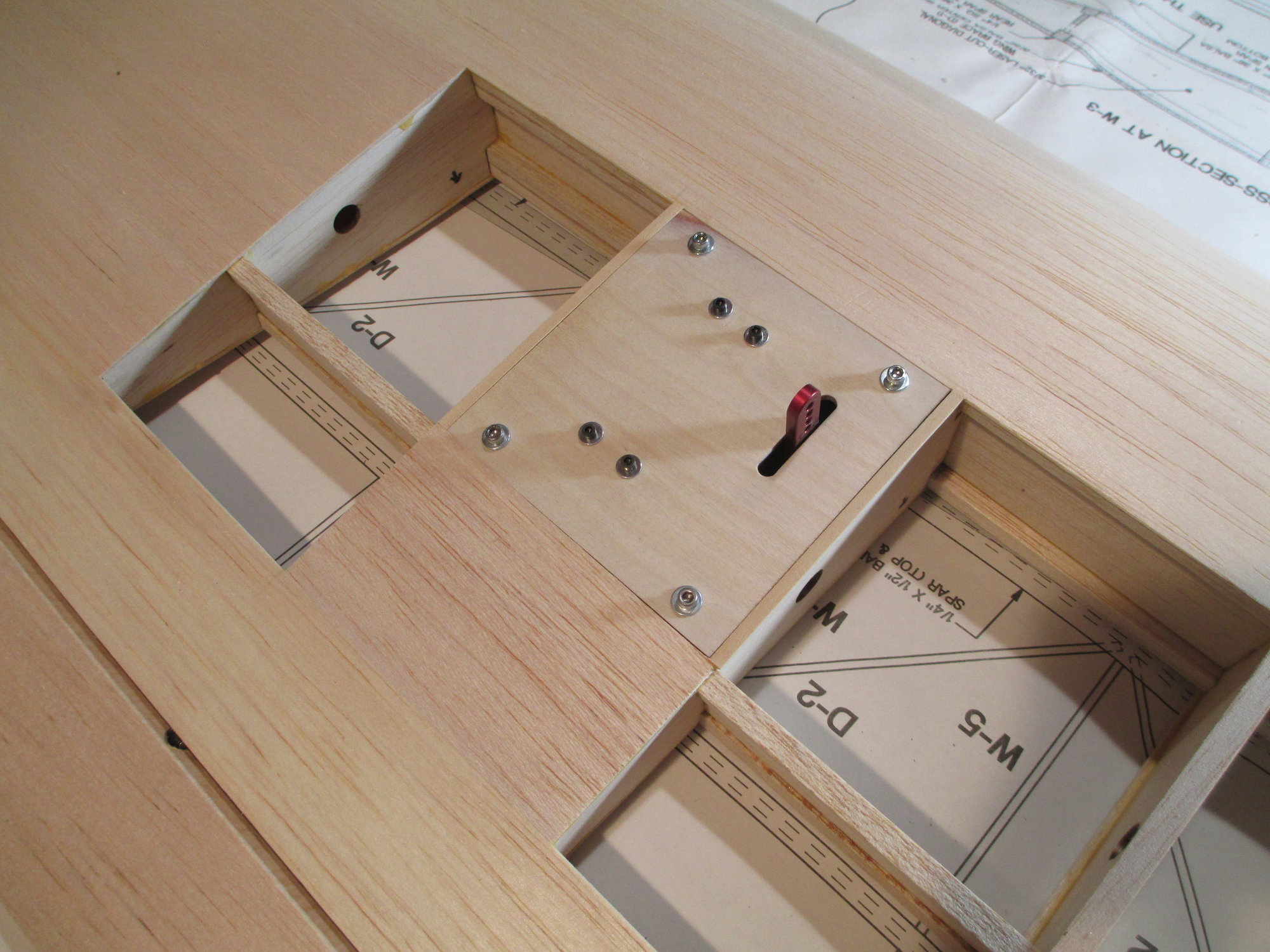
The slot that the servo arm slips through may have to be lengthened once they are operational, but for now it is good.
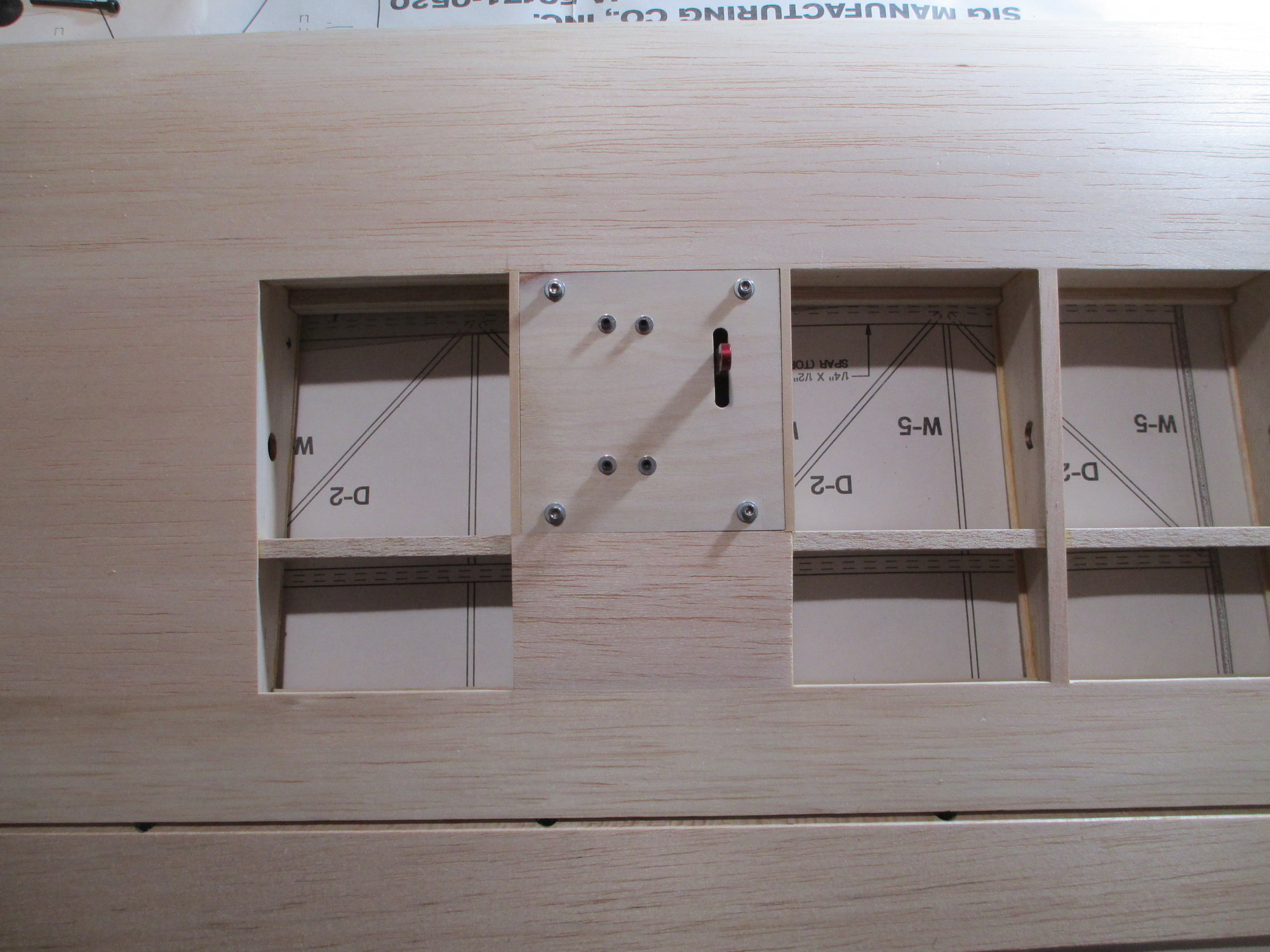
I realize that I don't have the same color hardware, that will all be rectified on final assembly...
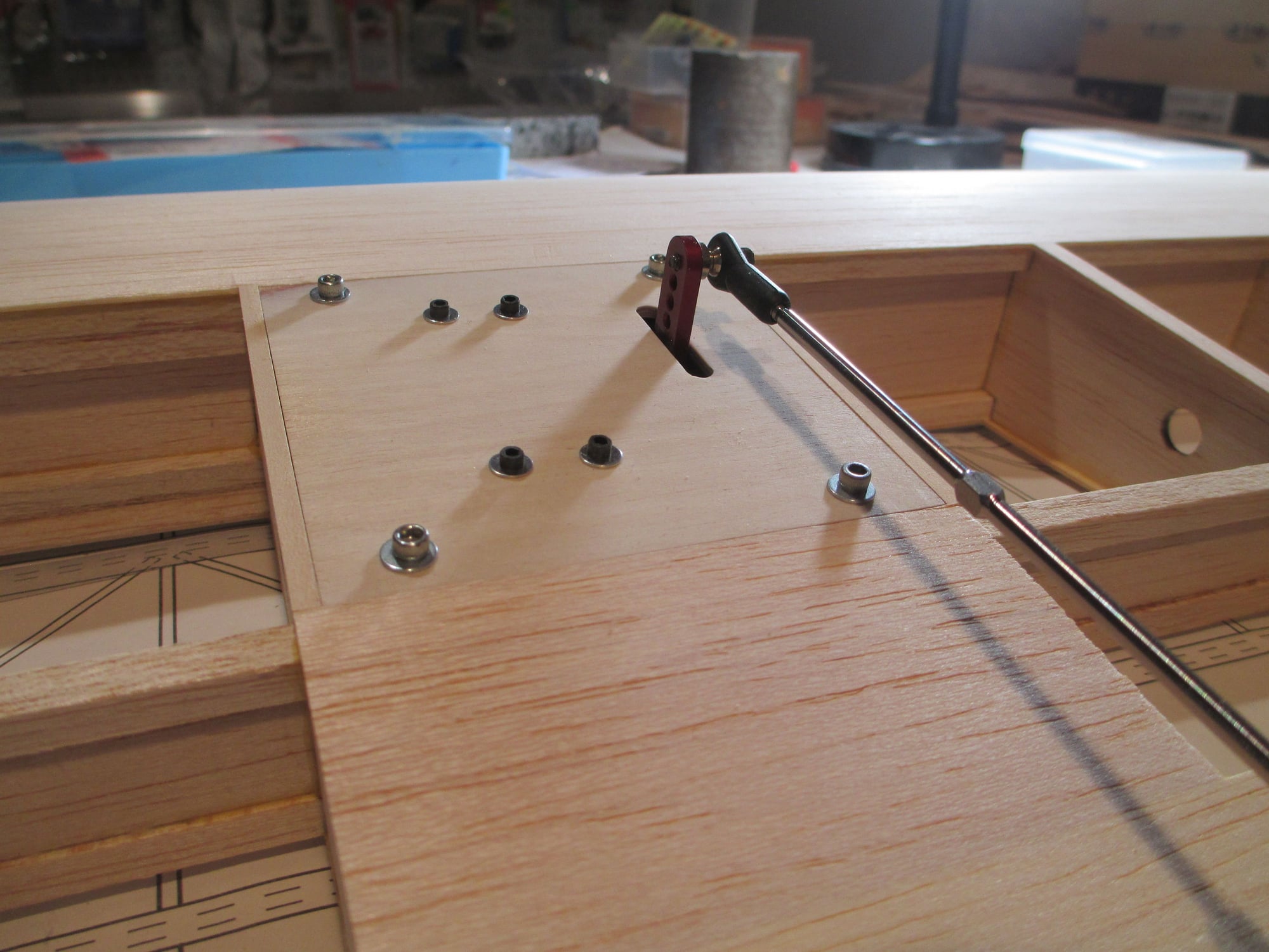
With the titanium turnbuckle in position, I can now determine the exact placement of the aileron horn. More on that later...
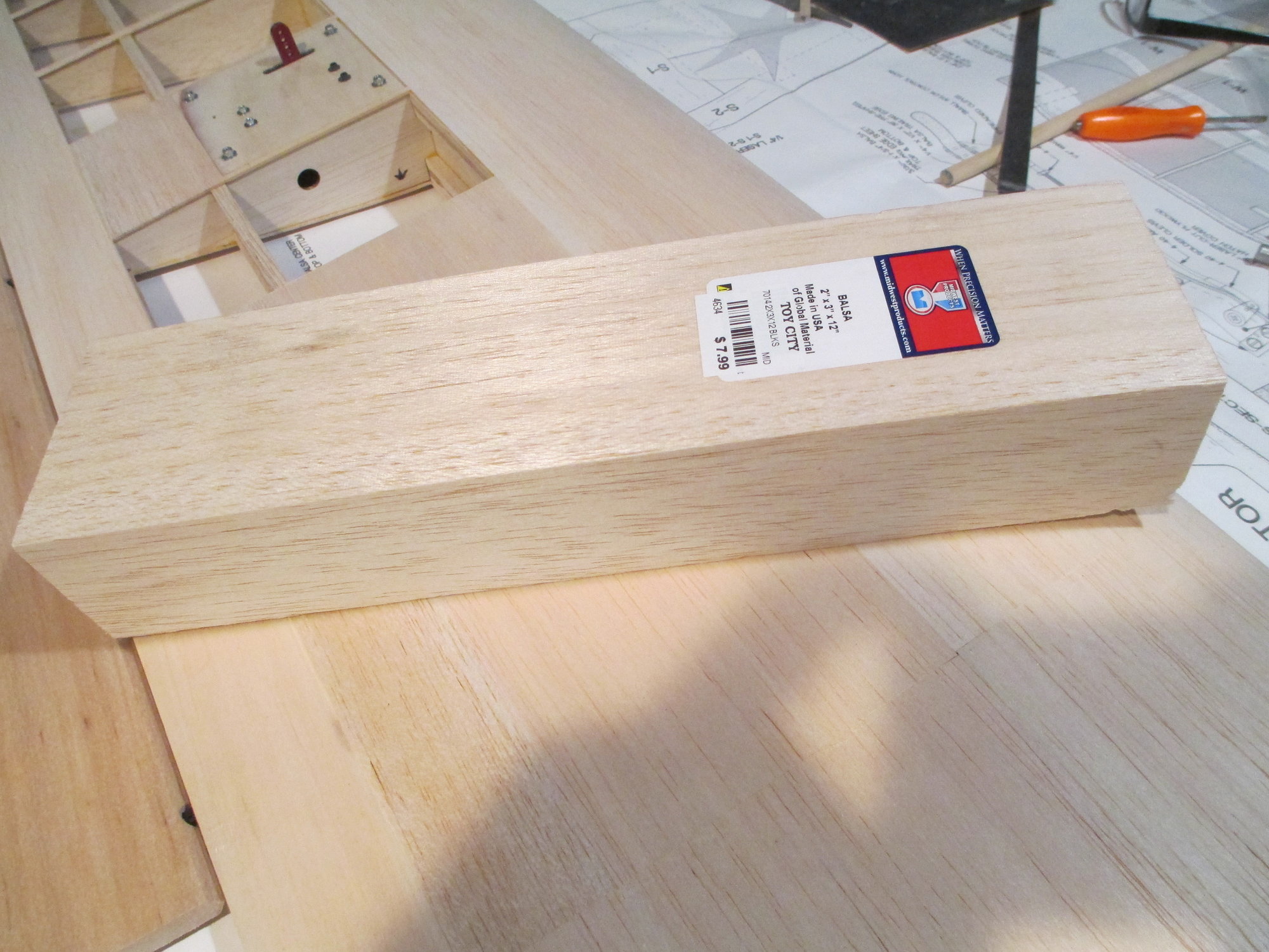
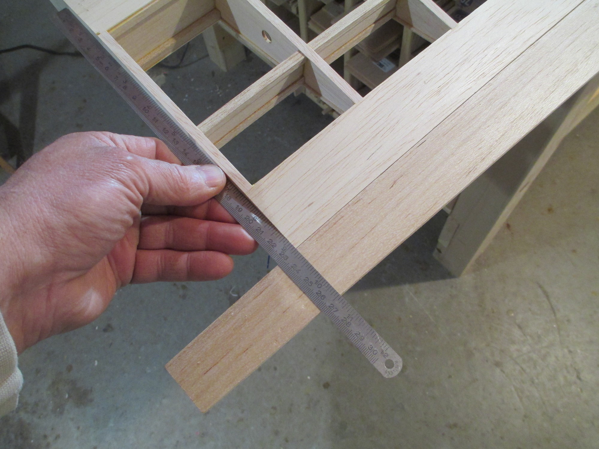
To some, it may look like a block (2'' x 3'' x 12") of balsa, but to me it looks like a wing tip!!!
Last edited by VincentJ; 03-26-2019 at 02:53 AM.
The following users liked this post:
Wully (12-21-2021)