


New TopRC T-28 Trojan
 12-08-2023, 06:27 AM
#176
Member
that's a nice shop table. wish mine was that big. i try not to add up how much money i have in these planes lol it makes me feel better.
make sure to check your nose gear strut spring. i tried to compress the nose strut and using all my force i could maybe just barely get it to compress. took out the spring and the grease they used was more like glue. cleaned out the strut and the spring and put regular grease on. now i can actually get it to compress. still may be too stiff will test it out later.
retract and door programming was very simple. had that done really quick. the gear seem to be very strong. pleased with them so far.
had to cut the cowl significantly to clear the steering servo push rod. didn't mind bc need to cut it for cooling anyway.
picture of the main gear door servo install. in the manual they had the servo rotated 90* from the position mine is in.
 12-08-2023, 01:01 PM
#177
what torque servo are you using for now steering? I forgot to order one for that. I'm hoping not to cut the cowl like you did but will see when I get into it.
My oleos are the same, both mains and nose, can't compress them at all the scissor links are flat against the leg. I'll have to have a look how to pul lthem apart and do what you suggested. I have read that the blue type of grease is what you use.
That is just one of my benches, there is another slightly smaller then others around the edge of the shed plus some smaller ones on casters.
That bg one is also on industrial casters so I can move it where ever I need it to be.
Last edited by planenutzz; 12-08-2023 at 07:07 PM.
12-08-2023, 07:15 PM
#178
I will prob put the servo through the top of the mount to reduce how far it protrudes down and instead of ball links will use heavy duty clevises which will keep the depth it protrudes down but will also prevent any twisting forces from the servo arm to the tiller arm on the leg.
Hopefully that will mean I won't need to cut a big hole in the bottom of the cowl.
I decided to use a Dualsky DS589 for the nose leg steering, it is 15kg torque @ 7.4V so should be ample. Good value at $46 AUD.
Hopefully that will mean I won't need to cut a big hole in the bottom of the cowl.
I decided to use a Dualsky DS589 for the nose leg steering, it is 15kg torque @ 7.4V so should be ample. Good value at $46 AUD.
12-10-2023, 06:12 PM
#179
Member
sorry been out of town. not sure the torque or the servo off hand but it's a powerful one. was the nose steering servo in my big elite aerosports havoc turbine.
that's a good idea mounting upside down. should definitely cut down on how much it protrudes out.
that's a good idea mounting upside down. should definitely cut down on how much it protrudes out.
12-10-2023, 10:24 PM
#180
I saw on the TopRC FB page a chap doing one of these that he painted a deep blue, he did as I suggest wit hthat servo but looks like he also added a spacer to reduce that depth even further which I had been thinking of doing anyway.
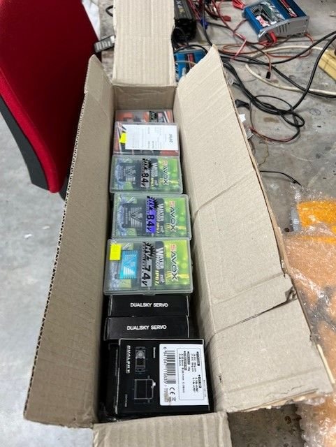
First of my box of goodies arrived from DA, powerbox, fuel pump, kill switch , some Tees and 2 tubes of hysol.
Servos should arrive end of the week. Will order some battery packs next pay day.
First of my box of goodies arrived from DA, powerbox, fuel pump, kill switch , some Tees and 2 tubes of hysol.
Servos should arrive end of the week. Will order some battery packs next pay day.
12-11-2023, 05:21 PM
#181
Servos are on the way and should be here tomorrow.
I got a revised quote for the Ramoser VarioProp with a spare set of blades.
Eye watering given our poor exchange rate but if I want a scale prop got to pay.
That will be a next year item.
I got a revised quote for the Ramoser VarioProp with a spare set of blades.
Eye watering given our poor exchange rate but if I want a scale prop got to pay.
That will be a next year item.
12-12-2023, 12:57 AM
#182
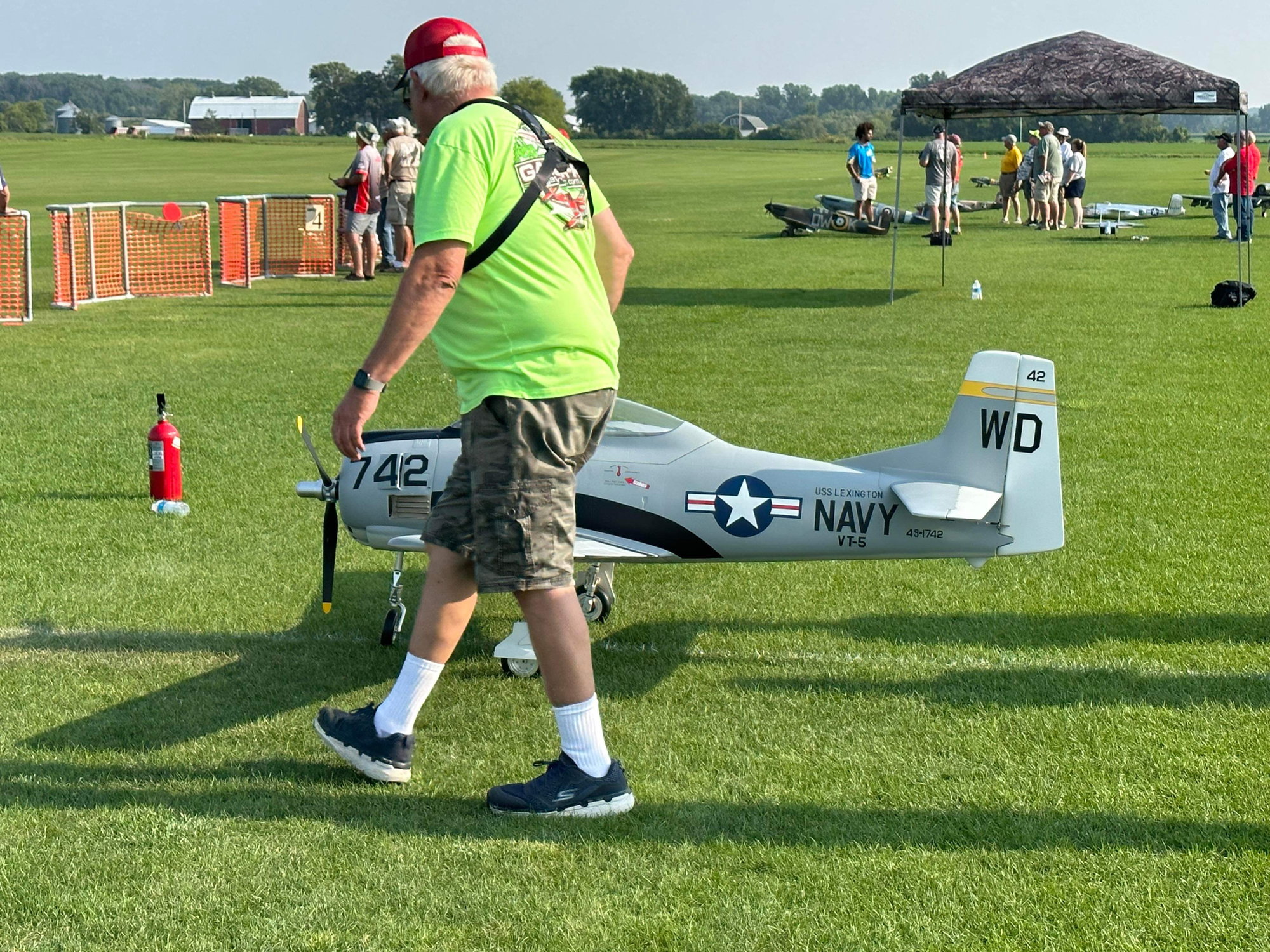
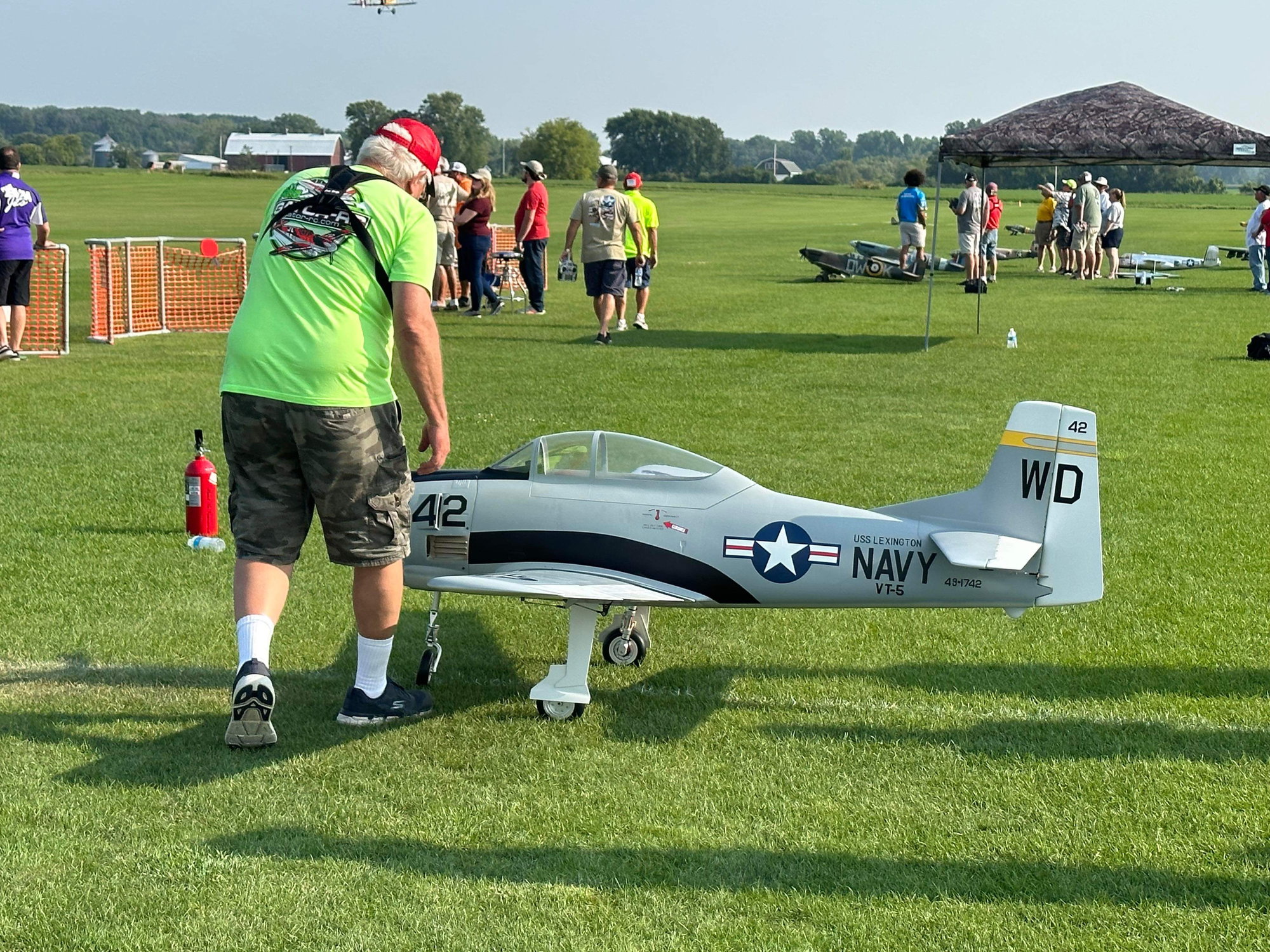
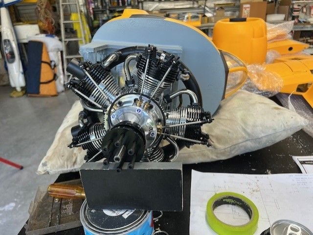
Decided to get mine out of the box and familiarise myself with it. Boy it is a big beast.
Can't say I like the way the cockpit tub sits in, I will need to do a little work on that area.
Nose retract mount will get a bit of a trim and some CF reinforcement.
Engine box will have a carbon fibre bandage around that will also extend out onto the from former to lock all of that in. Possibly out a 2mm plate of aluminium to the firewall to help compression of the timber. Not sure on that yet.
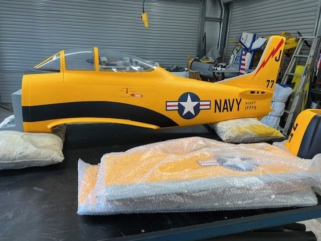


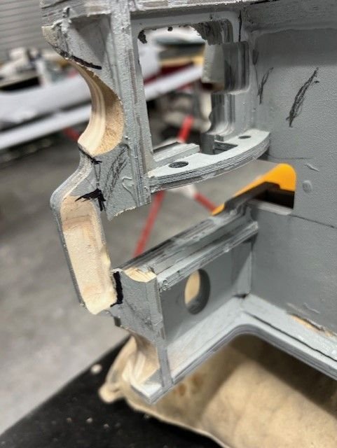
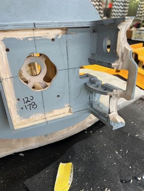
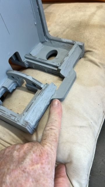 This front section I am pointing to will be removed mostly to allow clearance for the UMS 180 collector ring. Retract unit itself will add great structural strength to this area.

Carbon fibre bandage to be applied where I am indicating I did the same on my TopRC FW-190. A bead of hysol may be applied around the inside of the fuz where the front former is. Not sure on that yet.
A little gusseting will be done to reinforce the nose gear mount area.
Can't say I like the way the cockpit tub sits in, I will need to do a little work on that area.
Nose retract mount will get a bit of a trim and some CF reinforcement.
Engine box will have a carbon fibre bandage around that will also extend out onto the from former to lock all of that in. Possibly out a 2mm plate of aluminium to the firewall to help compression of the timber. Not sure on that yet.
This front section I am pointing to will be removed mostly to allow clearance for the UMS 180 collector ring. Retract unit itself will add great structural strength to this area.Carbon fibre bandage to be applied where I am indicating I did the same on my TopRC FW-190. A bead of hysol may be applied around the inside of the fuz where the front former is. Not sure on that yet.
A little gusseting will be done to reinforce the nose gear mount area.
 12-13-2023, 01:02 AM
#184
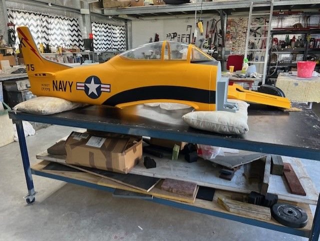
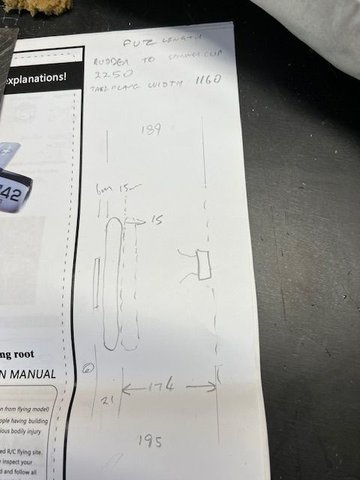
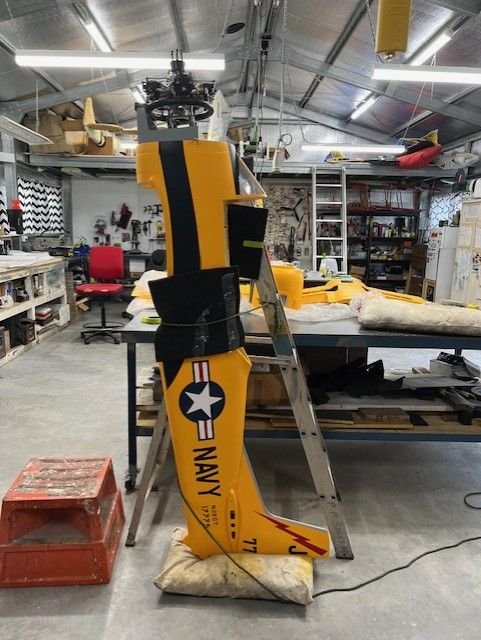
I put cowl on and taped rudder in position so I can measure how long this thing is to see if it fits in the trailer. I made a guestimate of where I think the engine hub will end up, prop hub and spinner cup to come up with 2250mm - fits!
With stabs on the tailplane width is 1160mm, again it fits.
Starting taking some measurements to work out how far out the engine needs to be mounted and how much to trim off the front nose gear mount for collector ring clearance. I expect the prop hub will need to be be a bit forward of scale location but will have to live with that. Should not be too bad hopefully.
Just need to get engine out and measure base of engine mount to the collector ring then I can work it out.


110mm to cowl lip
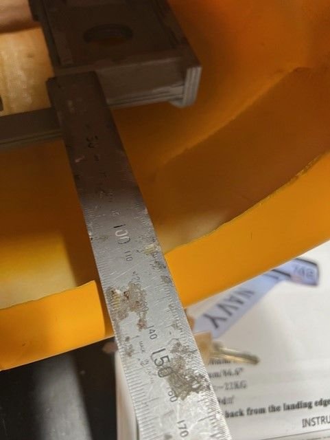
135mm to cowl lip


Prop hub does protrude quite a bit on full size

With stabs on the tailplane width is 1160mm, again it fits.
Starting taking some measurements to work out how far out the engine needs to be mounted and how much to trim off the front nose gear mount for collector ring clearance. I expect the prop hub will need to be be a bit forward of scale location but will have to live with that. Should not be too bad hopefully.
Just need to get engine out and measure base of engine mount to the collector ring then I can work it out.
110mm to cowl lip
135mm to cowl lip
Prop hub does protrude quite a bit on full size
12-13-2023, 05:20 AM
#185

My Feedback: (6)
Using my handy bathroom scales, it took roughly 50lbs of pressure to get the oleos to move. so maybe if you land in a power dive you could get them to move a fraction of a second before the airframe explodes.
I have ordered a selection of springs from Ali Express of varying wire sizes and hopefully I can give you guys a more workable solution that results in actual functioning oleos.
I initially ordered 12mm dia. springs, but those turned out to be a fraction of a mm too large to fit. Expecting a new shipment of 11mm dia. springs any day now.
12-13-2023, 12:02 PM
#186
Member
the springs are definitely an issue. love to hear what you find with new ones.
getting my fuel system together. just about done with it just need to route the lines. going with 2 24oz tanks.
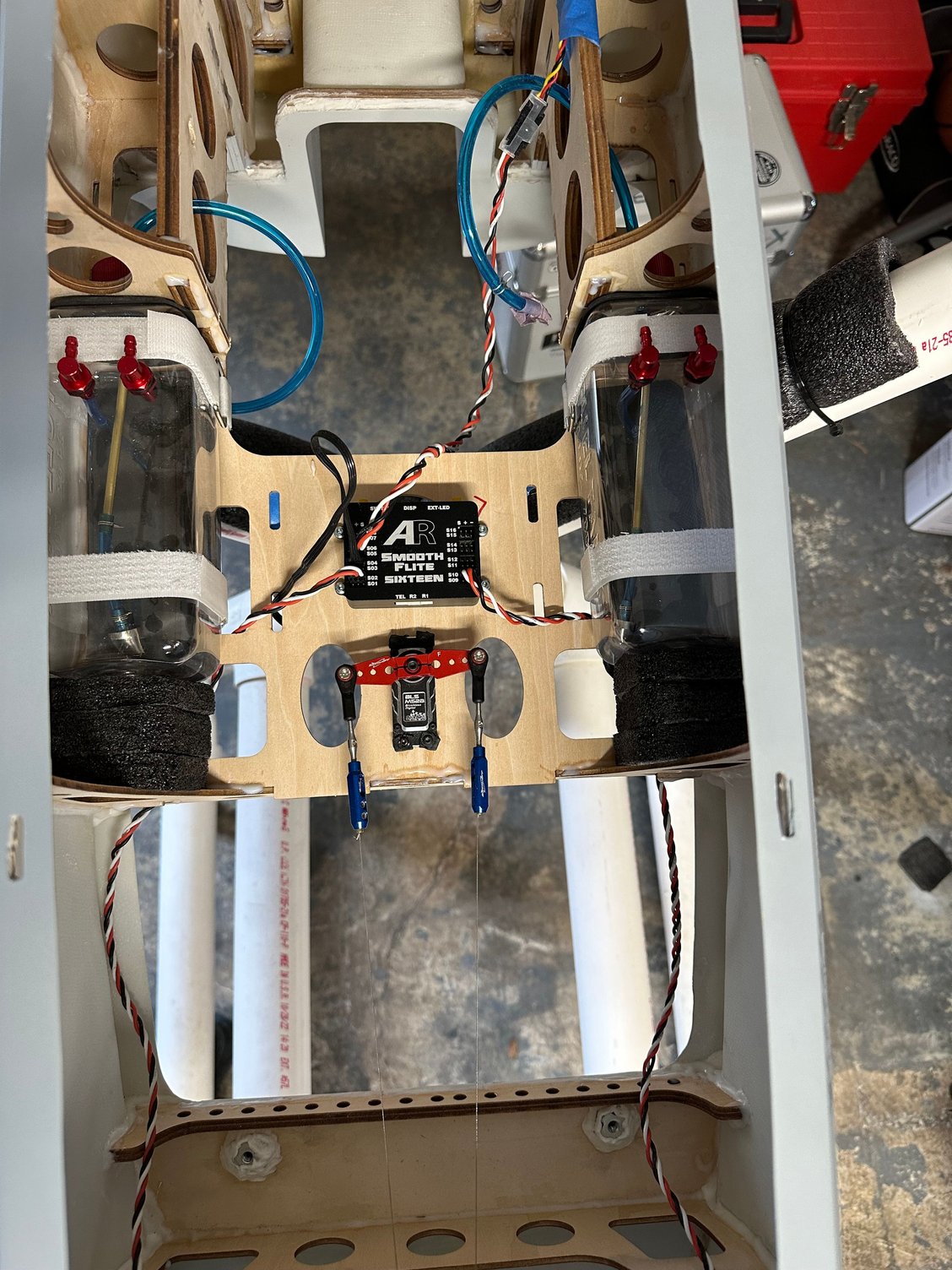
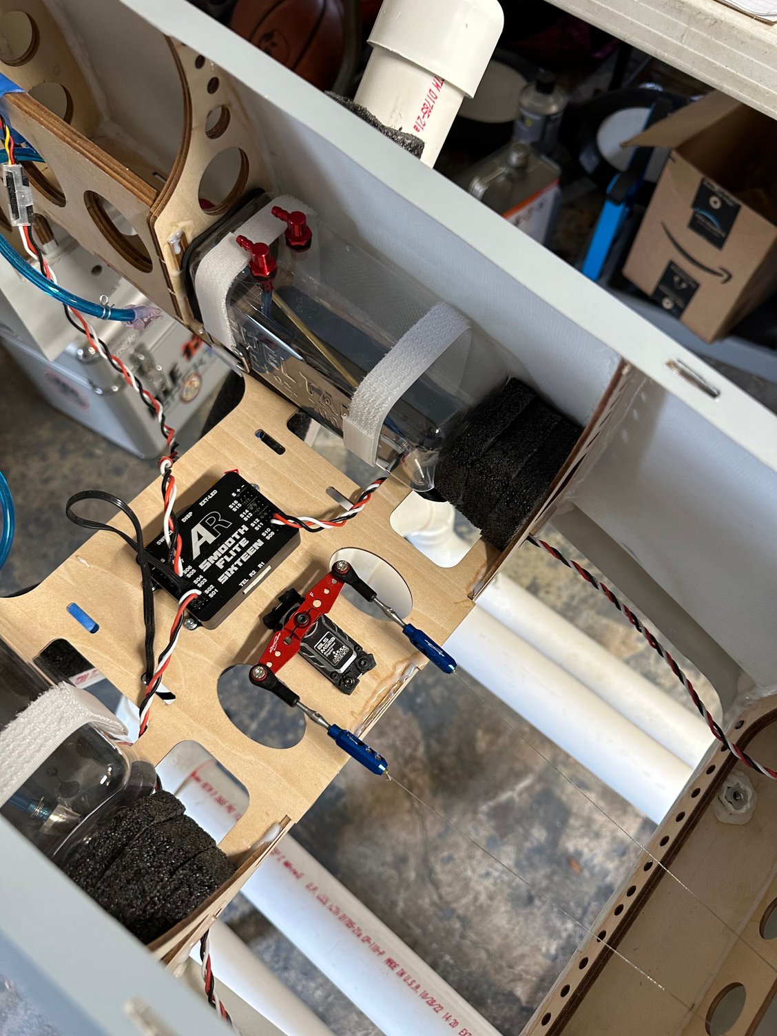
getting my fuel system together. just about done with it just need to route the lines. going with 2 24oz tanks.
12-13-2023, 01:27 PM
#187
Using my handy bathroom scales, it took roughly 50lbs of pressure to get the oleos to move. so maybe if you land in a power dive you could get them to move a fraction of a second before the airframe explodes.
I have ordered a selection of springs from Ali Express of varying wire sizes and hopefully I can give you guys a more workable solution that results in actual functioning oleos.
I initially ordered 12mm dia. springs, but those turned out to be a fraction of a mm too large to fit. Expecting a new shipment of 11mm dia. springs any day now.
I have ordered a selection of springs from Ali Express of varying wire sizes and hopefully I can give you guys a more workable solution that results in actual functioning oleos.
I initially ordered 12mm dia. springs, but those turned out to be a fraction of a mm too large to fit. Expecting a new shipment of 11mm dia. springs any day now.
That would be great info to have. McMaster Carr have good selection but won't ship O/S, I can get sent to a friend in the US and on shipped if need be.
Will be interesting to see what the quality of the springs from aliexpress are like.
cheers
me
12-13-2023, 01:32 PM
#188
2 x 24 tanks will give you just a bit less than the 1500mL tank supplied. I have no idea of the fuel consumption the UMS 180 but may use original tank plus a 24 ounce header tank. Still to be worked out.
12-13-2023, 06:26 PM
#189
Have been considering the dilemma of collector ring to nose mount clearance and how that then dictates how far the prop hub distance will be from the cowl lip.
As it currently stands removing the timber to just in line with wear the retract unit will mount will have the hub face much too far forward and it would look ridiculous.
So how to mitigate that as much as possible.
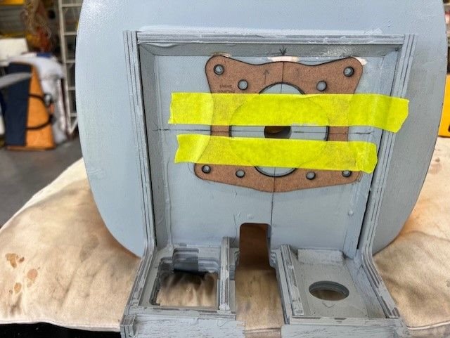
Need a mock up that mimics the collector ring outline, use that to position on firewall and mark out where4 the ring would meet the front face of the retract mount, draw that profile on the timber so that I would be following the curve & grinding out a channel and the collector ring then sits recessed to an extent within said ground channel
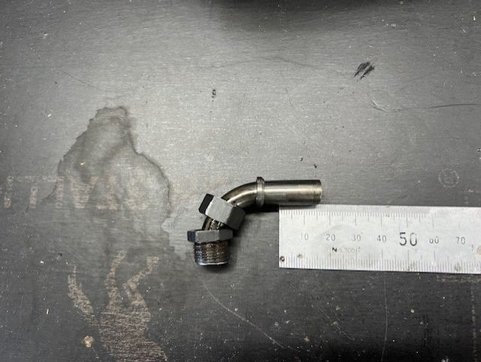
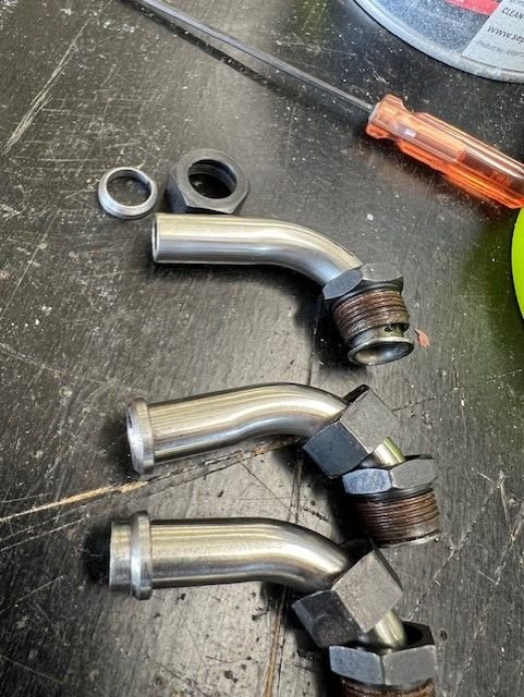
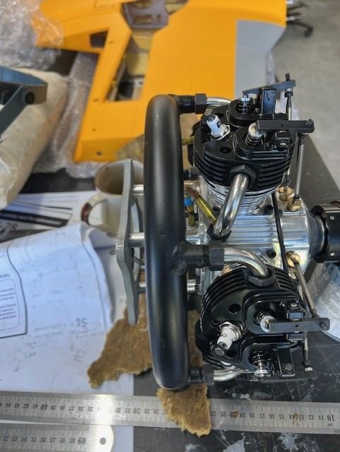
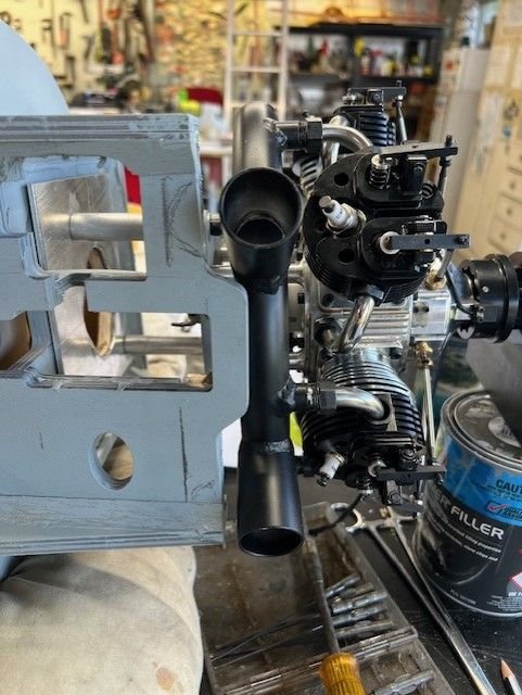
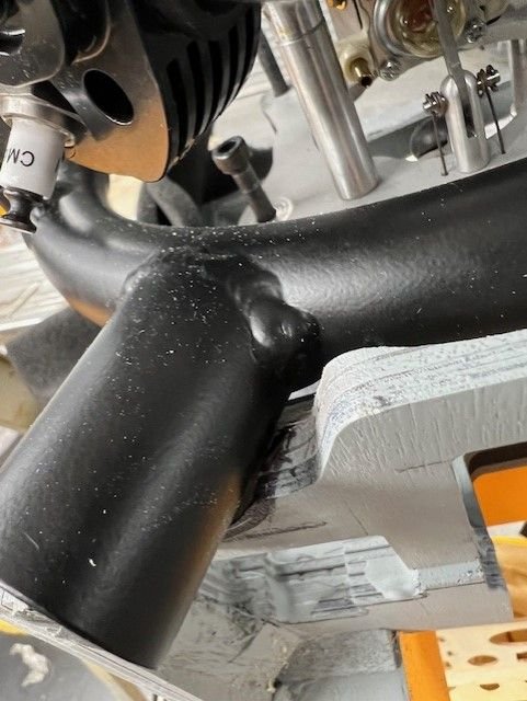
So while pondering the above I looked at the engine and how the collector ring is attached with its associated pipes. Note the pipes are not welded to the ring, the pipe has a collect with a nut that inserts slightly into the collector ring. These pipes are quite long and there is nothing to stop collector ring being brought forward towards the cylinder head.
How far forward could it go? 15mm works well and provided suitable clearance from the head. Looking at the pipes 15mm could easily be cut.
The collector ring as it is has 6mm clearance from the mounting plate rear face. Bringing the collector ring forward 15mm realises a new distance of 21mm.
Does not totally mitigate the prop hub being too far forward but it helps a lot. I think if I can then create that channel recess and gain say another 5, maybe 7mm then it is where I would be reasonably happy as a good compromise. I really do not want to push that nose leg rearward if I can help it. I know another builder went that route, moved the leg rearward a lot and did a lot of timber surgery. It is an option to maybe gain another 5mm but would not be comfortable going further.
From there work out standoff distance needed. At the moment I am looking at 64mm but with luck that may get 10mm cut off.
My other concern is making sure that if the engine is brought forward that I still have clearance for headers and the rockers. I think I will be ok as the one from Gator had the bigger and longer 210 fitted by bring the engine way forward even further than what I am looking at.
Quite enjoy this part, working out how to develop a solution from a tricky problem. Pretty much what I do for a living anyway")

Collector ring pipe that comes from the cylinder head. Can cut 15mm off these easily.
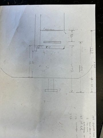
Workings
Numbers so far. Gotta be sadety concious

As it currently stands removing the timber to just in line with wear the retract unit will mount will have the hub face much too far forward and it would look ridiculous.
So how to mitigate that as much as possible.
Need a mock up that mimics the collector ring outline, use that to position on firewall and mark out where4 the ring would meet the front face of the retract mount, draw that profile on the timber so that I would be following the curve & grinding out a channel and the collector ring then sits recessed to an extent within said ground channel
So while pondering the above I looked at the engine and how the collector ring is attached with its associated pipes. Note the pipes are not welded to the ring, the pipe has a collect with a nut that inserts slightly into the collector ring. These pipes are quite long and there is nothing to stop collector ring being brought forward towards the cylinder head.
How far forward could it go? 15mm works well and provided suitable clearance from the head. Looking at the pipes 15mm could easily be cut.
The collector ring as it is has 6mm clearance from the mounting plate rear face. Bringing the collector ring forward 15mm realises a new distance of 21mm.
Does not totally mitigate the prop hub being too far forward but it helps a lot. I think if I can then create that channel recess and gain say another 5, maybe 7mm then it is where I would be reasonably happy as a good compromise. I really do not want to push that nose leg rearward if I can help it. I know another builder went that route, moved the leg rearward a lot and did a lot of timber surgery. It is an option to maybe gain another 5mm but would not be comfortable going further.
From there work out standoff distance needed. At the moment I am looking at 64mm but with luck that may get 10mm cut off.
My other concern is making sure that if the engine is brought forward that I still have clearance for headers and the rockers. I think I will be ok as the one from Gator had the bigger and longer 210 fitted by bring the engine way forward even further than what I am looking at.
Quite enjoy this part, working out how to develop a solution from a tricky problem. Pretty much what I do for a living anyway
Collector ring pipe that comes from the cylinder head. Can cut 15mm off these easily.
Workings
Numbers so far. Gotta be sadety concious
Last edited by planenutzz; 12-13-2023 at 06:30 PM.
12-15-2023, 05:58 AM
#190
Member
im sure you will get your engine mounting issues all sorted you seem to be quite the engineer with these things. looking forward to see what you come up with.
couldn't take it anymore. had to paint the gear white!

couldn't take it anymore. had to paint the gear white!
The following users liked this post:
marksp (03-03-2024)
12-15-2023, 06:05 PM
#191
I tend to take my time working things out, pretty at that side of things. ex RAAF so go figure.
The gear looks much better painted white, did you etch prime it first? I'll probably so same on mine.
I need to trim a bit of timber which is on top of the gear rail to fit the mains in, not a big deal. How far along the rails did you mount the mains? Based on where the upper door needs to be?
Too hot and humid to do anything plus im nursing a hangover, a mate came up yesterday as he bought a couple of my smaller models off me that I no longer fly and we had far too many beers last night .
Aircon and netflix day me thinks.
The gear looks much better painted white, did you etch prime it first? I'll probably so same on mine.
I need to trim a bit of timber which is on top of the gear rail to fit the mains in, not a big deal. How far along the rails did you mount the mains? Based on where the upper door needs to be?
Too hot and humid to do anything plus im nursing a hangover, a mate came up yesterday as he bought a couple of my smaller models off me that I no longer fly and we had far too many beers last night
. Aircon and netflix day me thinks.
12-21-2023, 01:13 AM
#192
Have been thinking that instead of mucking about cutting the nose retract mount back, recessing it and shortening the engine stub pipes to the collector ring why not do away with the collector ring and use flexibile pipes?
I'm sure it is doable.
I'm sure it is doable.
12-21-2023, 10:33 AM
#193
Senior Member
 12-21-2023, 05:44 PM
#194
If you look at the oleo scissor links, they sit almost flat against the leg. Spring compression is wayyyyy too strong. Also the clag 'grease' inside the oleo is binding them up.
Anyway back to measuring engine, firewall and etc and think I may have a plan, going back to almost Plan A.
- cut 15mm of stub pipes that go from cylinder head to collector ring. I got in touch with chap who repairs these here and he advised should be a good choice and cause no issues.
- cowl lip to hub face I will make it for 30 - 35mm. This will allow clearance of the wide scale T28 style blades on the VarioProp when set at say 14" of pitch.
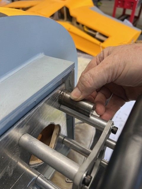
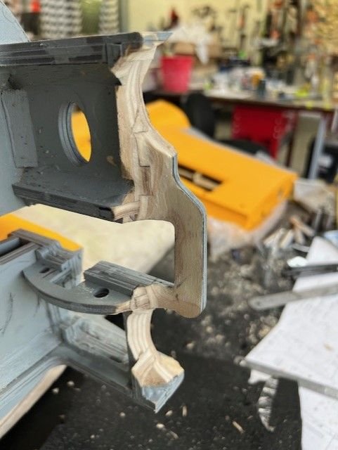
- I then cut back timber of nose leg as show in below pic
- stand offs will then be either 70 or 75mm. I may use a 5mm aluminium plate on the firewall which will take 5mm off length of standoffs.
I am getting confident this will work and will not interfere with nose leg and it's steering servo.

cheers
me
Anyway back to measuring engine, firewall and etc and think I may have a plan, going back to almost Plan A.
- cut 15mm of stub pipes that go from cylinder head to collector ring. I got in touch with chap who repairs these here and he advised should be a good choice and cause no issues.
- cowl lip to hub face I will make it for 30 - 35mm. This will allow clearance of the wide scale T28 style blades on the VarioProp when set at say 14" of pitch.
- I then cut back timber of nose leg as show in below pic
- stand offs will then be either 70 or 75mm. I may use a 5mm aluminium plate on the firewall which will take 5mm off length of standoffs.
I am getting confident this will work and will not interfere with nose leg and it's steering servo.
cheers
me
12-21-2023, 11:35 PM
#195
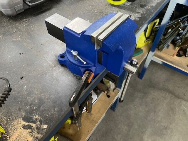
More pondering today. Bought myself a new vice as I did not have one, made some soft jaws for it too.
Prepared a piece of 3mm aluminium plate that will go over the timber firewall to prevent standoffs crushing the timber. I may attached it to the timber with a think coat of epoxy.
Marked holes for the UMS 180. Re-checked my proposed 15mm cut on the exhaust stubbs and checked to see I can still route ignition leads. Looks to be fine.
Also found my stash of stand offs. Interestingly they are drilled for 6mm bolts and I have 4 of those correct length. The stand off length is 75mm from timber forewall, less 3mm for the plate which means standoff need to be 72mm which is exactly what length they are. Maybe I had those machined way back knowing subconsciously this model would come along. Odd how things work out.
One thing I do not have is 6mm nylock nuts or 6mm nuts of any type. Nut & bolt shops are now closed till next week sometime. Oh well plenty of other things to get on with.
Merry Christmas all.
12-23-2023, 01:06 AM
#196
busy couple of days, replaced a flickering LED light batten in my shed. This is about the 8th one so far and installing a much better brand.
Trail fitting of the UMS 180 to see how much timber needs to be shaved and whereabouts. As stated in previous posts I will grind a channel that will accept the exit pipes of the collector ring.
The front lip piece of timber won't need to be cut off, just a recess so that the bottom part of the collector ring will fit into.
Cowl lip to hub face will be 30mm, yes I'd like it to be much closer, around 15mm would be great but that means cutting far too much timber out of the front and moving nose leg rearward as far as it would go.
As it is there will be some use of carbon fiber to reinforce the front mount.
I managed to shorten the stub exhaust pipes by 15mm and refit the collector ring though I almost stuffed the thread on the bottom fitting. Very close thing.
Had to get the x 3 glasses on and a very fine file to re-create the thread enough to get the nut started.
In fact the standoffs will be 52mm, not the 72mm I thought yesterday, I was measuring something else, just as well I double checked this morning and re-drew my plan.
Standoffs I am using are 50mm but will have 2 large face washers under them. Holes were only 5mm in the standoffs so had to drill those out for the 6mm bolts I am using. Pedestal drills come in handy.
You can see in the photos how far in the engine will go once I cut the channel.
Recalcitrant light replaced

Pipes shortened by 15mm, first one done at the bottom.

You can see how much closer the collector ring is now to the cylinder heads but still plenty of room for cooling and spark plug leads.
15mm end bits cut off the stub pipes
Stand offs drilled to accept 6mm bolts.

Plan & measurements
Trial fit using longer 72mm standoffs to see where I need to remove timber.

Pipes will be 23mm closer to the firewall once I am done. You can see rough marking out.
The lip stays, just a shallow recess to allow the collector ring to fit rearwards over it.
This shows just how much the engine will move towards the firewall.
It looks good.
Trail fitting of the UMS 180 to see how much timber needs to be shaved and whereabouts. As stated in previous posts I will grind a channel that will accept the exit pipes of the collector ring.
The front lip piece of timber won't need to be cut off, just a recess so that the bottom part of the collector ring will fit into.
Cowl lip to hub face will be 30mm, yes I'd like it to be much closer, around 15mm would be great but that means cutting far too much timber out of the front and moving nose leg rearward as far as it would go.
As it is there will be some use of carbon fiber to reinforce the front mount.
I managed to shorten the stub exhaust pipes by 15mm and refit the collector ring though I almost stuffed the thread on the bottom fitting. Very close thing.
Had to get the x 3 glasses on and a very fine file to re-create the thread enough to get the nut started.
In fact the standoffs will be 52mm, not the 72mm I thought yesterday, I was measuring something else, just as well I double checked this morning and re-drew my plan.
Standoffs I am using are 50mm but will have 2 large face washers under them. Holes were only 5mm in the standoffs so had to drill those out for the 6mm bolts I am using. Pedestal drills come in handy.
You can see in the photos how far in the engine will go once I cut the channel.
Recalcitrant light replaced
Pipes shortened by 15mm, first one done at the bottom.
You can see how much closer the collector ring is now to the cylinder heads but still plenty of room for cooling and spark plug leads.
15mm end bits cut off the stub pipes
Stand offs drilled to accept 6mm bolts.
Plan & measurements
Trial fit using longer 72mm standoffs to see where I need to remove timber.
Pipes will be 23mm closer to the firewall once I am done. You can see rough marking out.
The lip stays, just a shallow recess to allow the collector ring to fit rearwards over it.
This shows just how much the engine will move towards the firewall.
It looks good.
Last edited by planenutzz; 12-23-2023 at 01:09 AM.
01-01-2024, 09:59 PM
#197
Re-read the engine manual and it firmly states to not use standoffs so will use 3 x laminations of 18mm hardwood marine ply and will be using 6mm high grade bolts right through.
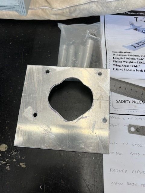
Made up a dummy exhaust ring template so I can start the slow job of trimming timber to allow collector ring to be recessed and keep engine rearward as muchg as possible without removing copious amounts of the timber.
I need to go about another 5mm.
Carbon fibre will then be used to beef it up.


Made up a dummy exhaust ring template so I can start the slow job of trimming timber to allow collector ring to be recessed and keep engine rearward as muchg as possible without removing copious amounts of the timber.
I need to go about another 5mm.
Carbon fibre will then be used to beef it up.
01-02-2024, 11:38 PM
#198
Did a trail check of the engine after doing some timber trimming for the exhaust outlet recess.
It is very close, about 5mm max should do it.
Standoffs are just to get correct distance, I will be using a lamination of marine ply.


It is very close, about 5mm max should do it.
Standoffs are just to get correct distance, I will be using a lamination of marine ply.
01-04-2024, 01:19 AM
#199
More fiddling getting the clearance I need for the collector ring. Even though I was able to reduce distance by 15mm with my CR mod I still need to remove a lot of timber.
Bottom qat the front where the lip is will get a 9mm plywood doubler as far as I can go and not interfere with the nose gear mount.
There will be 4 x gussets of 9mm ply to brace the nose mount plate. These will be locked in hard against the 54mm plywood engine mount lamination.
Grain will go fore and aft.
Most of the triangular gussets that were fitted are rubbish, not sure what glue they use but it is very rubbery.
Nose leg needs to be moved rearward 10mm approx. I'll wait till I get engine mounted properly then I can double check just how far it needs to move.
Anyway it is slow going but progress none the same.
Pics to show the progress.
Engine mount lamination using 3 x 18mm hardwood marine ply. These are oversise and will be belt sanded to a snug fit within the engine box ply protrusion.

The 54mm ply engine mount lamination will fit snugly where I have ground away the old gussets. It will be epoxied to the main firewall.
The curved brace below will be ground flush and a 9mm triangualr gusst will be glued in with hysol and will be a snug fit against the mount lamination.
The opposite side will will he gusset removed and another 9mm gusset glued in as per other side.
2 more go on far edge where existing triangle stock is. That stock is rubbish.
More than I would like but can't be helped.
Still in the process of trimming in this pic.

Looks like still a lot of timber left here but other side is a different story.

That is pretty much all the trimming

That is the distance, standoffs are to get distance only and will be replaced with a 54mm plywood lamination.

Later lurkers.
Bottom qat the front where the lip is will get a 9mm plywood doubler as far as I can go and not interfere with the nose gear mount.
There will be 4 x gussets of 9mm ply to brace the nose mount plate. These will be locked in hard against the 54mm plywood engine mount lamination.
Grain will go fore and aft.
Most of the triangular gussets that were fitted are rubbish, not sure what glue they use but it is very rubbery.
Nose leg needs to be moved rearward 10mm approx. I'll wait till I get engine mounted properly then I can double check just how far it needs to move.
Anyway it is slow going but progress none the same.
Pics to show the progress.
Engine mount lamination using 3 x 18mm hardwood marine ply. These are oversise and will be belt sanded to a snug fit within the engine box ply protrusion.
The 54mm ply engine mount lamination will fit snugly where I have ground away the old gussets. It will be epoxied to the main firewall.
The curved brace below will be ground flush and a 9mm triangualr gusst will be glued in with hysol and will be a snug fit against the mount lamination.
The opposite side will will he gusset removed and another 9mm gusset glued in as per other side.
2 more go on far edge where existing triangle stock is. That stock is rubbish.
More than I would like but can't be helped.
Still in the process of trimming in this pic.
Looks like still a lot of timber left here but other side is a different story.
That is pretty much all the trimming
That is the distance, standoffs are to get distance only and will be replaced with a 54mm plywood lamination.
Later lurkers.
01-05-2024, 06:20 AM
#200
Member
i cut the nose retract tray all to pieces too. a little reinforcement and yours will be fine. the radial will be awesome.
got it on its feet yesterday. i previously worked in the nose strut spring it was super stiff. got whatever glue/grease they used off of it and put some better grease in and now it will compress some. the mains are just as bad. pushing it around yesterday it was just bouncing all over the place.

got it on its feet yesterday. i previously worked in the nose strut spring it was super stiff. got whatever glue/grease they used off of it and put some better grease in and now it will compress some. the mains are just as bad. pushing it around yesterday it was just bouncing all over the place.